

THE RISE in crime rate is normal to the overall western world, and is apparently relevant to wealthiness instead of to poverty as was formerly assumed by a lot of us.
For this reason, nowadays, the possibilities of your house being burgled tend to be higher without a doubt, and becoming more significant. Each and every householder really should as a result provide severe thing to consider to be able to safeguarding his home through a highly effective alarm system.
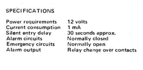
In this home intruder alarm circuit the CMOS IC provides adequately low power drain (lower than 1 mA) to generate battery functioning prospective. And by virtue of the high noise immunity of CMOS (half supply voltage) the unit is not vulnerable to false alarms as a result of lightning flashes etc.
In addition the inherent dependability of integrated circuits and you have the basis of a quite simple, but more efficient, system. Three modes of operation are designed into the unit which usually performs the examples below:
ALARM MODE
Microswitches or reed relays fitted to have closed contacts once the door, etc, is closed.
Almost all contacts are usually wired within a series loop in a way that if any door or window is opened up, the loop will probably be broken triggering the alarm.
The series loop needs to be wired among points A and E on the circuit.
SILENT ENTRY
This mode of operation permits the owner, whenever leaving the premises, 30 seconds to open and close the front door prior to the alarm mode is turned on.
It also enables the owner 30 seconds to disable the alarm right after getting into through the front door.
Hence the front door microswitch is not really as part of the normal alarm loop but to its own 'silent entry' loop.
The silent entry switch needs to be wired among point B and E on the circuit.
EMERGENCY
Within this mode, any contact closure from a switch or sensor (eg fire, smoke or gas detector) will certainly straight away sound the alarm.
Wire switch(s) across points F and D. The finished alarm 'unit must be positioned in a fairly very well covered up place near to the 'silent entry' door.
The alarm bell is the most suitable positioned in a high, well concealed rather than easily available place.
Since high voltages are usually produced throughout the bell 'make and break' contacts it is considerably better make use of a separate bell battery of appropriate voltage instead of to connect it over the main system battery.
How it Works


The home intruder alarm circuit possesses three various modes of operation as explained in the article. When power is first used, i.e. normal alarm mode enabled, capacitor C2 at first is without charge.
This momentarily elevates the inputs of IC1/1 to +12 volts. The capacitor then charges gradually through R1 and the voltage introduced to IC1/1 drops significantly to zero.
The output of IC1/1 will probably be zero if the input is over 7 volts, and at +12 volts if the input is less than 5 volts. There exists a small linear region, about 6 volts, wherein the output changes from zero to +12 volts.
Along with the values provided to C2 and R1 a delay of 30 seconds is made available which can be altered, if needed, by changing C2. During this delay opening or closing the silent entry door is not going to impact the level displayed to pin 6 of IC1/2.
An RS flip-flop is created by IC1/2 and IC1/3 wherein the control inputs (pins 6 and 9) are usually low (zero volts).
On first switch ON pin 9 is pulled up momentarily to +12 volts by C4 prior to going back to zero.
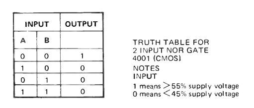
This offers a "1" to the input of IC1/3 and for that reason its output will be low (see Table below ). Due to the fact pin 7 is at zero, and pin 5 is also at zero, (linked to pin 10) the output of 1C1/2 is going to be high. Because this is connected to the input of IC1/3 the flip-flop will likely be locked into the state where IC1/3 output is low.

The only method the flip-flop could be reversed is for the input to pin 6 to go high. Nevertheless through the first 30 seconds, as discussed above, the output of IC1/1 is low. For this reason, opening or closing the silent entry door during this time period is not going to set the flip-flop and switch on the alarm.
Following this 30 second period, opening the silent entry door will show a "1" to pin 6 which will allow the flip-flop to change state. Closing the silent entry door will now have no impact and the flip-flop will continue to be set.
The high output of IC1/3 will permit C6 to charge gradually to +12 volts through R9. When this voltage gets to 6 volts (around 30 seconds) it is going to trigger the output of IC1/4 to go low (presuming the normal alarm loop is shut down). The low output of IC1/4, by way of emitter follower Q1, pulls in relay RL1 triggering the home intruder alarm circuit.
Once the relay closes contacts RL1/1 lead it to latch on, and only getting rid of power by pressing PB1 will reset it. If at any time the normal guard loop is broken, when the alarm is activated, a "1" is presented to pin 13 of the IC1/4 evoking the output to go low and the relay to close.
Once the emergency switch is closed the base of Q1 is delivered to zero and the relay closes and latches. This process is going to take place irrespective of whether the alarm is allowed or not.
Diodes D1 and D2 discharge capacitors C2 and C6 correspondingly through SW1 when it is in the "off" position, hence making sure that the 30 second delay is actually acquired.
Resistors R6, 7 and 12 safeguard the CMOS IC towards voltages in excess of the supply rails. Capacitors C3, 5, 7 and 8 add further more security towards false activating as a result of lightning and many others.