


Here we talk about electrical relay, that is mainly built using an electromagnet and a set of contacts which are spring-loaded and changeover type. So what happens is, when we switch ON or OFF this electromagnet using a DC power then that spring-loaded system is pulled or released accordingly by this electromagnet. Because of this, the changeover action takes place on the end terminals of these contacts. Now if we have some external electrical load connected to these contacts then that load will also turn ON or OFF as per the relay electromagnet switching.
Now here in this post, we go deep and learn everything about how relays work inside electronic circuits how we can correctly find the pinouts of any relay using a meter and how we can wire it properly in circuits.
Introduction
So if we want to flash a lamp, switch an AC motor or do any similar operation then relays are always useful for such tasks. But what happens is, beginners who are new to electronics often get confused when they try to check and understand relay pinouts or when they want to connect a relay correctly inside an electronic circuit with a driver stage.
In this article we will go through some basic rules that will help us in properly identifying relay pinouts and also understand how exactly a relay works. So let us move ahead and start discussing!
Relay Working
The following information will help you understand how an electrical relay works:


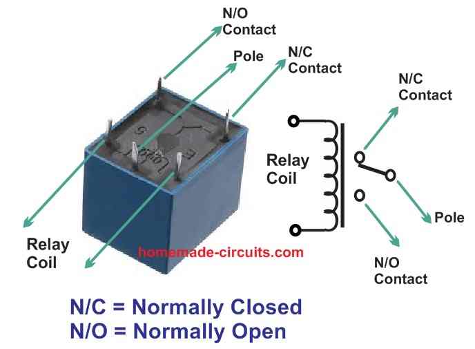
Here we take a relay mechanism, right? So this thing mainly has two big parts inside—one is a coil and the other is a spring-loaded contact that is free to move on a pivoted axis, OK?
Now here we see that there is a central pole. This pole is not fixed but hinged or pivoted in such a way that when we apply voltage to the relay coil then this pole quickly moves and connects with one of the side terminals. That side terminal is called the N/O contact, which means Normally Open.
Why does it do that? Because the relay coil when powered produces a strong electromagnetic pull which forces the pole iron to get attracted and shift toward the N/O contact.
But when we cut off the power to the relay coil then the electromagnetic pull disappears, right? So the pole has no reason to stick to the N/O contact anymore. Instead it quickly disconnects from the N/O and moves back to another terminal. That second terminal is called the N/C contact, meaning Normally Closed.
So this N/C position is actually the default position of the relay contacts. Why? Because when there is no electromagnetism then the pole naturally stays in the N/C position due to the spring tension in the metal. The spring is always trying to keep the pole attached to the N/C terminal when the coil is not energized.
Now what happens during ON and OFF switching? The pole just keeps moving back and forth between N/C and N/O. If the relay coil is ON then the pole jumps to N/O. If the coil is OFF then the pole moves back to N/C. This alternates based on the power state of the coil.
Inside we have the relay coil wound tightly over an iron core. The moment we pass DC through this coil then it acts like a strong electromagnet. This electromagnetic force quickly pulls the spring-loaded pole toward itself, making the contacts switch positions as explained earlier.
Now this moving pole which is under spring tension, is the main switching component here. Its end is taken out as one of the relay pinouts.
The other two contacts N/C and N/O work as the complementary terminals. So these two will either connect or disconnect from the central relay pole, depending on whether the coil is powered or not.
Also these N/C and N/O contacts are extended out from the relay box as external pinouts, so we can easily use them in our circuits.
The rudimentary simulation below depicts the manner in which the relay pole travels depending on to the magnetic coil when turned on and off using an input supply voltage. We clearly observe that the central pole is originally attached to the N/C contact, but as soon as the coil is powered, the pole is dragged downwards owing to the coil's electromagnetic activity, pushing the central pole to be connected to the N/O contact.

Ok, so here we see that basically in a relay, we got three main contact pinouts. That is, first we got the central pole then one is N/C and the other is N/O. These are the switching contacts of the relay.
Now besides these three, we have two more pinouts which are connected to the coil of the relay. These two are responsible for energizing and activating the relay.
So this type of relay is what we call an SPDT relay. That means Single Pole Double Throw. Why? Because here we got just one central pole but it can switch between two different contacts, one being N/O and the other being N/C. That is why the term SPDT.
Now in total, how many pinouts does an SPDT relay have? We count and see—one central moving contact then two side contacts (N/O and N/C) and finally, two more for the coil. So all together we got 5 pinouts in an SPDT relay and that is how the whole thing is arranged.

How we can Identify Relay Pinouts and how we can Connect a Relay
Now normally what happens is and sadly this is true, that most of the relays which we see, they do not have proper markings on them so this becomes a big problem for people who are new in electronics because they cannot recognize the relay pinouts, then they do not know how they should use that for the correct purpose.
So what are the pinouts that we have to identify? These will be like this, step by step:
- The two pins of the relay coil.
- The common terminal or we call that the "Shared Pole Pin."
- The N/C (Normally Closed) terminal.
- The N/O (Normally Open) terminal.
Now, here, we will see how we can find the correct pinouts of a normal relay using a simple method:
First we take a multimeter then we turn that to the Ohms mode. It is best if then we set that to 1K range.
Then we take the meter probes and touch them to any two pins of the relay randomly. We keep trying like this until then we find two pins where the meter shows some resistance. This resistance will usually be anywhere between 100 ohms and 500 ohms. So when then we see this, we understand that these two pins are the coil pinouts of the relay.
Now after we find the coil pins, then we go ahead and do the same process with the remaining three pins of the relay.
We keep checking until then we find two pins that show continuity, meaning they are connected when the relay is in its normal state, without any power. These two pins will surely be the N/C (Normally Closed) terminal and the pole terminal because inside the relay, there is a spring that keeps the pole connected with the N/C pin when then the relay is off.
Now after we are sure of the N/C and pole pinouts, then we just need to look for one more pin which will be sitting somewhere around these two, mostly in a triangular pattern with them.
So finally what happens is, in this triangular arrangement, the middle pin is normally the pole pin of the relay and since we already marked the N/C pin then naturally, then the last remaining pin will be our N/O (Normally Open) pin. So now we have identified all the relay pinouts properly.
The simulation below demonstrates the manner in which a standard relay may be connected with a DC voltage source between its coils and a mains AC load over its N/O and N/C contacts.

So now we got these three contacts, right? But to be very sure we can do one more thing. We take the relay coil, we give it the exact voltage it needs then we take a meter and we check the N/O side to see if it is showing continuity or not. If it does then we are 100% sure about these contacts.
Now this simple way we just saw, we can use it for any relay whether we do not know its pinout or it has no labels on it. We just follow this same method and we can easily find out its pins.
So now we already understood how a relay works and how we can find out its pinouts. But there is something more we must look at. We should now check out the most common type of relay, the one that we see mostly in small electronic circuits. And not just that we must also see how we can correctly connect it.
The Common type of Relay PinOut Made in China. It is found in Blue color also. We also call it 5-pin Blue cube relay SPDT.


How We Can Wire Relay Terminals
Now we have a diagram that shows how we can connect this relay with a load, right? So what happens here is, when we give power to the relay coil then its N/O contacts close and that makes the load switch ON. But this will not happen just like that, we also need to connect a proper supply voltage along with the load.
Now this supply voltage which we put in series with the load must match the load’s specifications. If the load is something that works on DC voltage then we must use a DC supply, right? But if the load is made for AC mains operation then this supply voltage must be either 220V AC or 120V AC depending on what the load requires.

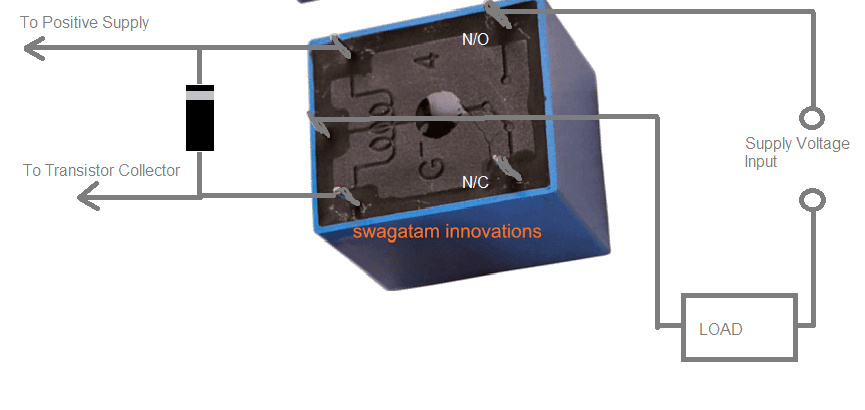
Why we always see a Diode across a Relay Coil, and why that is so much Crucial
Now whenever we use a relay inside any circuit, you must have surely noticed that always, always we have some diode or sometimes a capacitor compulsorily attached parallel with the relay coil.
That diode we call flyback diode or some people also say freewheeling diode. But why do we put this diode there? The main reason is that diode is the savior of the driver transistor. It protects the transistor from the deadly reverse EMF that comes from the relay coil.
Maybe sometimes you must have thought, why always a diode is sitting across the relay coil? What is so important about that? Now we will explain everything, step by step.
The secret is hidden inside one very special property of inductors. This property is very interesting but at the same time, it can become extremely dangerous for the circuit.
So we all know that, just like how capacitors can store electric charge, inductors also have this special ability to store DC electric energy inside their winding. And not just that, the more number of winding turns an inductor has, the more energy it stores.
A relay coil is also a type of inductor. And since it has a large number of turns in its winding, its ability to hold stored energy is also quite huge.
Now let us understand what happens when we operate the relay using a transistor.
When we switch ON the driver transistor then the relay coil also gets switched ON and at the same time, its winding starts storing DC voltage inside itself.
But here is where the big problem starts. When we switch OFF the transistor then what happens? The voltage that was stored inside the relay coil gets no path to go out and now it desperately tries to escape somewhere.
At this moment, the relay coil behaves like a fully charged battery and it tries to discharge that stored energy through anything it finds connected across its terminals. This is what we call "relay reverse back EMF."
Now the problem is, this back EMF is not normal. Its voltage can suddenly become much higher than the actual DC voltage we had fed to the relay coil.
Since the transistor is directly connected with the relay, this massive back EMF now starts forcing itself into the transistor, trying to push through the emitter/collector junction. And the worst part is, this voltage is in reverse polarity, meaning it is negative in nature.
Because it is negative, it does not go in the normal way. Instead it forcefully tries to enter from the emitter towards the collector and this is something that the transistor is not designed to tolerate. The result? The transistor gets instantly blown due to this sudden high-voltage shock.
So now what can we do to stop this? Very simple! We add a flyback diode or a freewheeling diode across the relay coil.
This diode acts like a safety valve. A normal 1N4007 diode is more than enough for most relay applications, even up to 30-amp relays.
So when the relay is ON then the diode remains in a negative bias condition which means it does nothing, it just sits there quietly. But when we switch OFF the relay then the back EMF suddenly comes out from the coil.
At that moment, the diode becomes forward biased, meaning now it becomes an easy escape route for the back EMF. The back EMF quickly finds a way through the diode and the diode short-circuits the EMF, completely killing it.
So in this way the deadly back EMF of the relay coil is safely cancelled and our transistor remains fully protected from any kind of damage.
But if we do not have a diode then no problem! We can also use a high-value electrolytic capacitor in the same place.
The capacitor will do the same work. It will provide a short-circuiting path for the back EMF and will protect the transistor from getting burned.
So that is why we always, always see a diode across a relay coil and why it is so much crucial.
What happens in the event the relay is powered directly from a power source without the incorporation of a driver transistor?
Let us say we do not use a driver transistor, and we simply give power straight from a power supply to the relay, ok? No in this case, we must still put a freewheeling diode right across the relay coil.
Why? Because when the relay coil is turned off then it will create a back EMF in the reverse direction. This back EMF may try to enter the power supply or the connected circuits, right?
And if that happens then there is a risk of damaging delicate electronic parts, ok?
How to Find the Relay Flyback Diode
Now this part is tricky because we see there is no exact formula to calculate or pick the relay flyback diode, right? But we can still understand the basic idea, ok?
The rule we follow here is that the back EMF current cannot go beyond the actual current rating of the relay coil. But, the voltage—yes that may go much higher, right?
If we want a simple answer then a 1N4007 works for most relay driver circuits where the relay is below 24V and has a coil resistance over 100 ohms, ok? Why so?
This is because the 1N4007 diode has a PIV (Peak Inverse Voltage) of 1000V and its current rating is 1 ampere. Normally the back EMF produced by a relay coil does not cross these limits so the 1N4007 can handle it easily.
For example let us say we have a big 12V relay with a 100-ohm coil. Then the current passing through the coil would be:
I = 12 divided by 100 = 120mA, right?
So when the relay turns off then the back EMF current will be much smaller than this 120mA, ok? That means the 1N4007 can safely take care of this reverse current without any issues, right?