In this post we are going to discuss how we can build a simple but powerful 40-watt automatic LED street light circuit that will work on its own, ok? Then when night comes, it will switch ON automatically, and then when the sun rises, it will switch OFF by itself. So we do not have to do anything, it will work all by itself. The design is made by me.
Now how does this work? So, during the day, the sunlight falls on the solar panel and the panel converts this light into electricity. This electricity is then used to charge a battery which gets stored energy. Now when night comes, this stored energy in the battery is used to power the LED lam, which lights up the streets. This means no electricity bill, no manual switching and completely free energy from the sun, right?
Why Solar Panels Are Important Today?
Today solar panels and PV cells are becoming very common. Everywhere people are using solar energy in different ways. Then in the future, we will see even more people using it daily. One of the most useful ways of using solar power is for street lighting. Instead of using grid electricity which costs money, solar-powered street lights can work without any running cost.
So here we will build a solar street light system with all standard features and below we explain everything clearly.
- LED Lamp Specifications – What We Need For The Light
- Here we list down all the important details about the LED lamp:
- Voltage – 12V (We will use a 12V, 26AH Battery).
- Current Consumption – 3.2 Amps at 12V.
- Power Consumption – 39 Watts (Using 39 pieces of 1-Watt LEDs).
- Light Intensity – Around 2000 Lumens (Good brightness for street lighting).
This means our LED lamp is strong enough to give bright light and can run for many hours using the stored power in the battery.
Charger/Controller Specification – What We Need For Charging The Battery
Now, we need a proper charger and controller circuit so that the battery is charged correctly and does not get overcharged or discharged too much. Here are the details:
Input – We will take 32V from the solar panel. The solar panel should have an open circuit voltage of 32V and a short circuit current of 5 to 7 Amps.
Output – The charger will give a maximum of 14.3V to the battery and limit the current to 4.4 Amps.
Battery Full Cutoff – When the battery reaches 14.3V, then charging will stop automatically (this is set using P2).
Low Battery Cutoff – When the battery voltage falls below 11.04V then system will turn OFF to protect the battery (this is set using P1).
Float Charging – After the battery is fully charged, then circuit will switch to float charging mode at 13.4V so that the battery stays charged but does not get overcharged.
Automatic Day/Night Switching – A Light Dependent Resistor (LDR) sensor is used to detect daylight. Then when the sun sets, then LDR will activate the LED light and then when the sun rises, it will switch the light OFF automatically. This is done by selecting an appropriate value of resistor R10.
What We Will Do First?
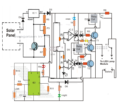
Now in this first part, we will study and build the solar charger/controller circuit. This includes the over-voltage protection, low-voltage cutoff and the automatic day/night switching system. Then when we finish this part we will move to the LED driver section and final connections.
Now let us start step by step.


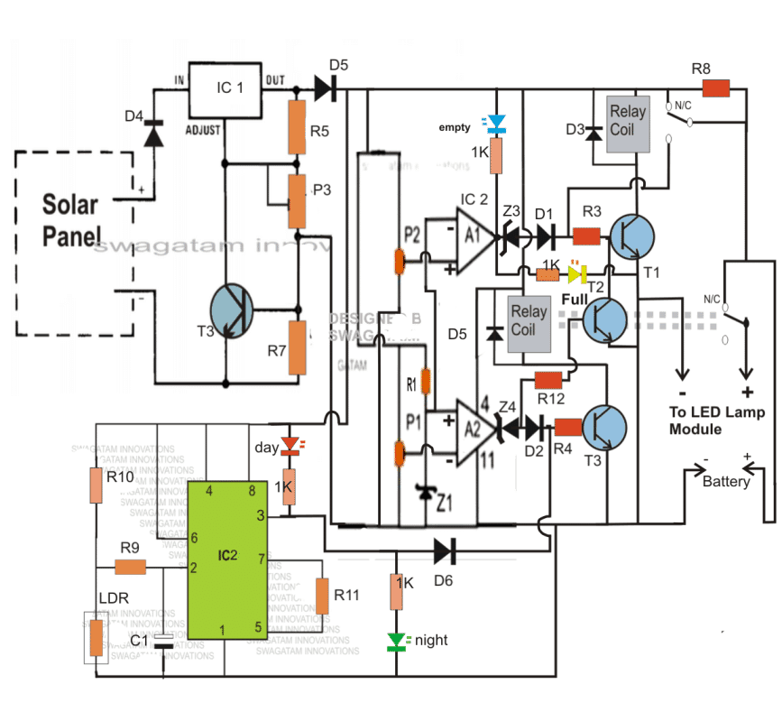
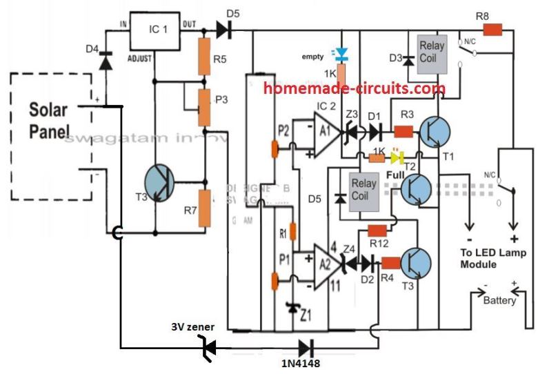
Simplifying the Design by Eliminating the IC 555 LDR stage
The above configuration may be significantly simplified by removing the IC 555 section and wiring the daytime relay shut OFF transistor straight to the solar panel positive, as illustrated below:

Parts List for the 40 watt Solar LED Street Light Circuit
| Component | Value/Type | Description |
|---|---|---|
| IC1 | LM317 | Adjustable Voltage Regulator |
| IC2 | LM324 | Quad Op-Amp IC |
| T1, T2, T3 | BC547 | NPN Transistors |
| T3 (Solar Control) | BC557 | PNP Transistor |
| D1, D3, D4, D5 | 1N4007 | General Purpose Diodes |
| D2 | 1N4148 | Fast Switching Diode |
| Z1, Z3, Z4 | Zener Diodes | Voltage Reference |
| P1, P2, P3 | Preset (Variable Resistor) | For Adjusting Cutoff Voltages |
| R1, R3, R5, R7, R8, R12 | Various | Resistors for Voltage Division and Current Limiting |
| Relay Coils | 12V Relay | Used for Switching Battery and Load |
| Solar Panel | 32V, 5-7A | Charges the Battery |
| Battery | 12V, 26AH | Stores Power for LED Lamp |
| LED Indicators | Red, Blue | Shows Battery Status (Full, Empty) |
How We Construct This Circuit? Step by Step With Tips
Now let us see how we can build this solar 40 watt LED street lamp circuit easily without mistakes, right? We will go step by step and I will also give some important tips so that you do not get confused.
Step 1: Setting Up the Solar Panel and Regulator Stage
First we take the solar panel which gives around 32V open-circuit voltage.
Then we use IC1 (LM317) which is an adjustable regulator. This IC is used to step down the solar panel voltage to around 14.3V which is suitable for charging the battery.
We adjust P3 to set this voltage properly.
T3 (BC557 PNP transistor) is used here for automatic switching. It helps to controll the charging process based on the sunlight.
Tip: When you solder the LM317 make sure to use a heat sink because it may get hot when the battery is charging.
Step 2: Setting Up Battery Overcharge and Low Voltage Protection
We now come to the battery charging controller part.
The IC2 (LM324) is used to monitor the battery voltage continuously.
P1 and P2 are used for setting the low battery cutoff (11.04V) and full battery cutoff (14.3V).
Then when the battery gets fully charged then relay coil switches OFF and prevents overcharging.
But if the battery voltage falls too low then the other relay disconnects the battery from the LED lamp to avoid deep discharge.
Tip: You must Set P1 and P2 very carefully because wrong settings can either overcharge the battery or turn OFF the lamp too early.
Step 3: Automatic Day/Night Switching
Now for making the LED lamp turn ON at night and turn OFF in the morning, we use a Light Dependent Resistor (LDR). But in the simplified version we have eliminated this stage and used the solar panel voltage itself for the detection.
If you are using the 555/LDR stage then when sunlight falls on the LDR, it sends a signal to the op-amp which then turns OFF the LED lamp.
Then, when it gets dark, the LDR resistance increases and this makes the circuit turn ON the LED lamp.
This is controlled by selecting R10 properly.
Tip: Place the LDR in such a way that it only detects natural sunlight and not the street lamp’s own light. Otherwise it may flicker.
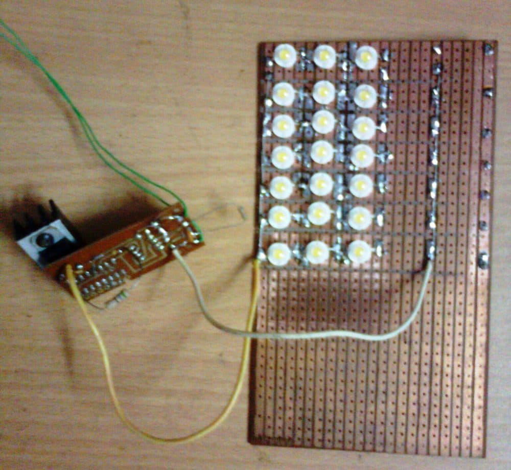
Step 4: Connecting the LED Lamp
Finally we connect the LED lamp module to the battery output.
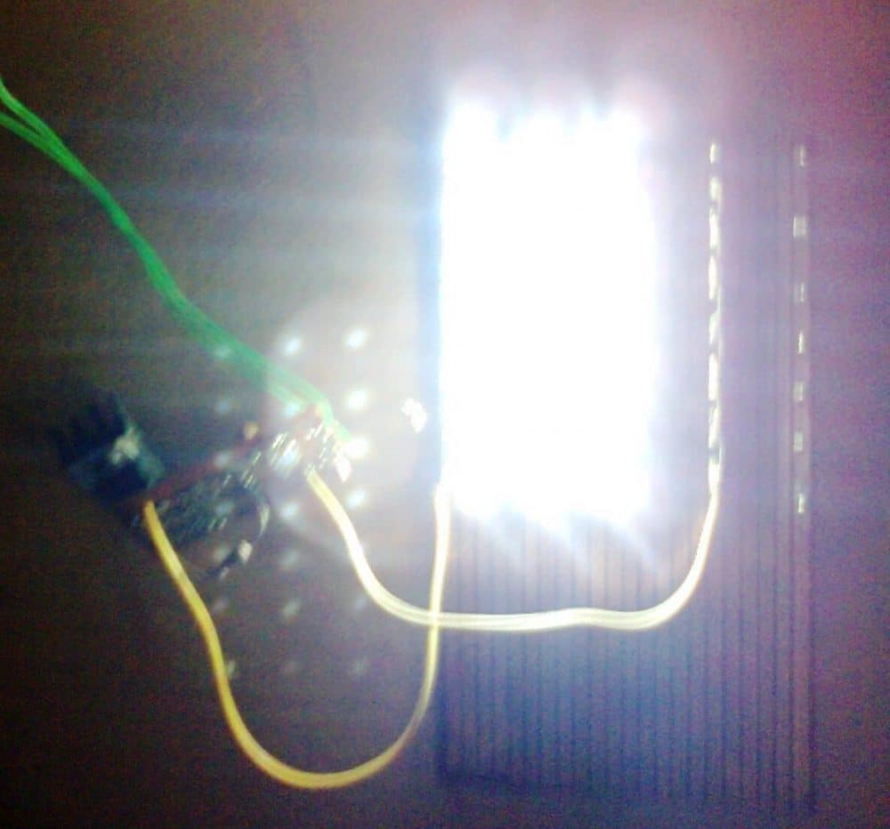
The 40 watt LED lamp consists of 39 LEDs of 1 watt each which gives around 2000 lumens of brightness.
Then, when the battery is fully charged, it stores enough power to keep the LED lamp ON throughout the night.
Tip: Always use thick wires to connect the LED lamp and battery because thin wires will heat up and cause power loss.
Now What We Should Check Before Switching It ON?
Check all connections twice. Then if everything looks fine, proceed.
Set the presets (P1, P2, P3) properly before first use. Then fine-tune if needed.
Place the solar panel in direct sunlight and check if the charging circuit is working.
Test the LDR function by covering it with your hand. The lamp should turn ON.
Check if the relays click ON and OFF properly at different battery levels.
Now once everything is set, we are ready to install the system and let it work automatically!
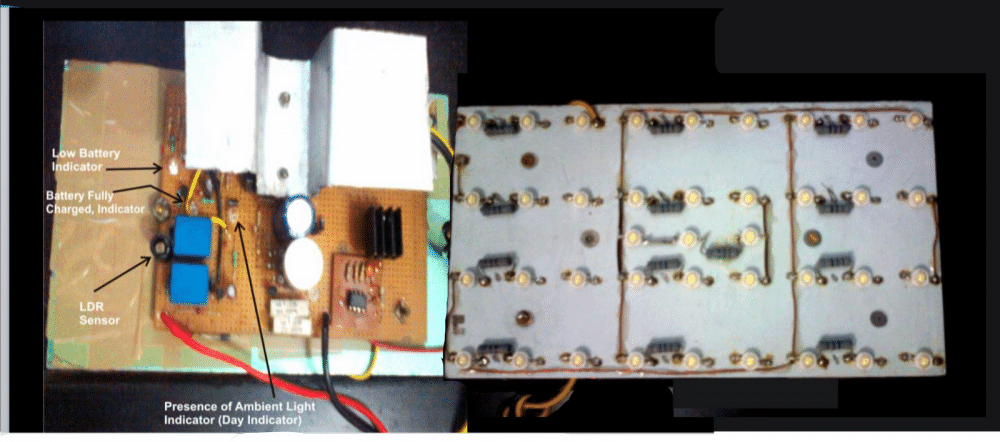
Prototype Images