


The publish talks about an appealing energy efficient lighting circuit design which switches ON only when it is logically needed thus really helps to save electricity, as well as raises the functioning life of the whole strategy.
The Design
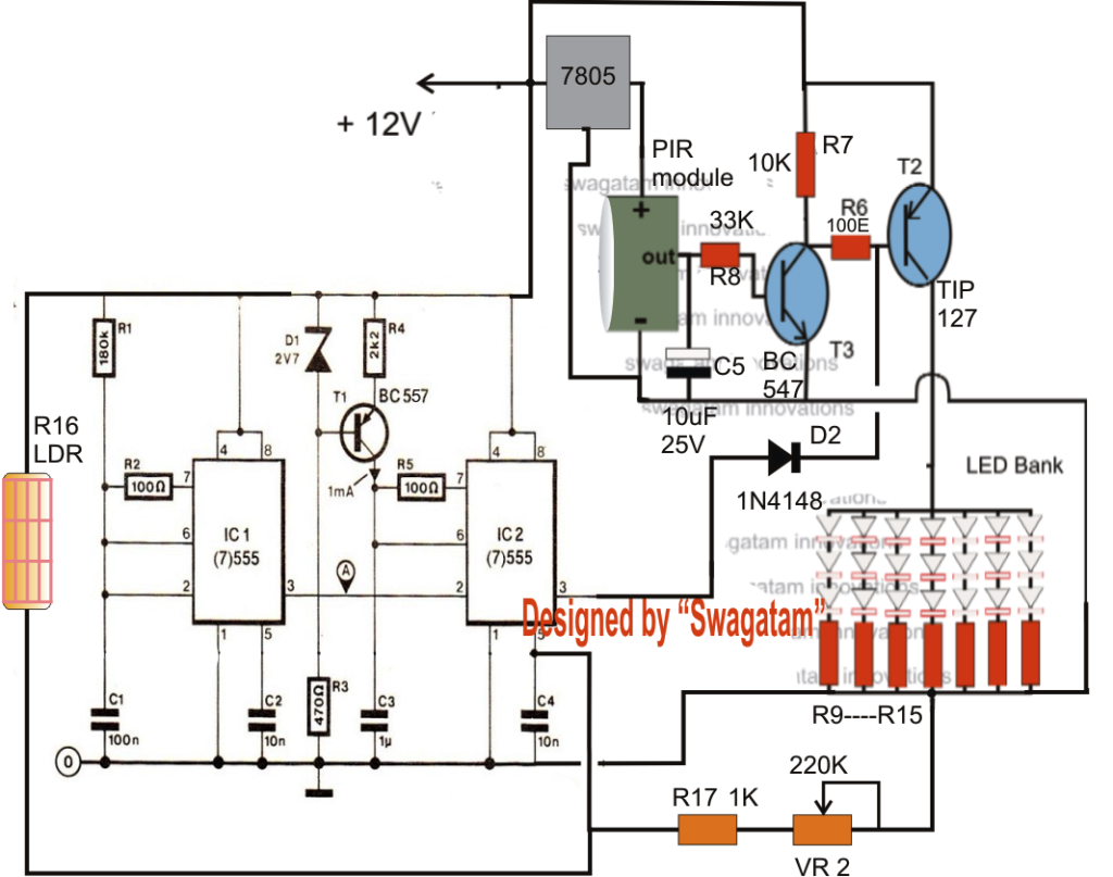
According to the demand the following less energy usage smart light circuit includes three different phases, viz: the PIR sensor stage, the LED module stage, and the PWM light controller stage comprise of a few IC555.
Let's recognize the the various levels with the following details:
The upper phase containing the PIR sensor module, and the connected circuit forms a regular passive infrared sensor step. In the existence of humans in the specific range, the sensor picks up it and it's internal circuitry transforms it to a potential improvement to ensure that it's fed to the base of the first NPN transistor.
The above trigger, switch on both the transistors, which often turn on the LEDs attached at the collector of the TIP127.
The above phase ensures that the lights are ON only throughout the occurrence of humans in the vicinity, and are turned OFF when there's nobody around. C5 guarantees the lights don't turn off instantly if you do not possess humans rather after a few seconds of delay.
Subsequent, we notice two IC 555 phases which can be set up as regular astable and PWM generator phases. C1 signifies the frequency of the PWM, while the R1 resistor can be utilized for optimizing the right reaction from the circuit.
The PWM output is given to the base of TIP127 transistor. This simply means, when the PWM pulses include wider pulses, keeps the transistor switched OFF for better durations, and vice versa.
It signifies, with broader PWMs, the LED could be weaker with their strength, and vice versa.
Everyone knows that the PWM output from a 555 IC (as designed in the right hand side section) is determined by the voltage level used at its control pin#5.
With greater voltages nearing the supply level can make the PWM output wider, while voltage nearing the zero mark tends to make the PWMs with minimum widths.
A potential divider phase made out of the assist of R16, R17 and VR2 achieves the above feature such that the IC replies to the external ambient light conditions, and produces the needed fully optimized PWMs for applying the LED dimming features.
R16 is really an LDR which ought to obtain Merely the light from external source getting into the room.
When the external light is bright, the LDR provides lower opposition therefore raising the potential at pin#5 of the IC, This encourages the IC to produce larger PWMs producing the LEDs develop dimmer.
Throughout low ambient light levsl, the LDR provides increased protection beginning the opposite outcomes, which is, right now the LEDs begin acquiring brighter correspondingly.
The 220K pot might be modified to get the finest feasible reply from the IC 555 level, according to personal choices.


In accordance with the demand, the above circuit needs to be operated from a battery, charged from a solar charger controller circuit. I have talked about a lot of solar charger controller circuits within this blog, the LAST CIRCUIT presented in the post can be used for the existing use.