


This logic detector probe circuit can be very helpful device for people who may choose to measure the logic levels of digital circuits frequently. Being an IC based circuit, it's applied in CMOS technology, its aplication is definitely more devoted to test circuits making use of the same technology.
The power for the recommended logic tester is gained from the circuit under test itself. On the other hand care is required to be taken not to put the power terminals in reverse, so when it is attached you should definitely set the colors of each one of the attaching wires.
For instance: Red Color, for the cable that hooks up with the positive voltage (CN2) and black color to the wire that is sent to 0 volts. (CN3)
Operational facts of logic tester probe with IC 4001
The function is simple. The 4001 CMOS incorporated circuit has four two-input NOR gates, 3 LEDs and a handful of passive elements applied in the design.
Achievement furthermore evolves into important in order that it really is easy to utilize while testing, for that reason the printed circuit needs to be in the prolonged in shape usually.
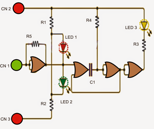
Seeking out the figure we notice that the sensing signal is carried out on CN1 terminal, which is usually attached to a NOR gate, whose inputs are actually in turn joined as a NOT gate or an inverter.
The inverted signal is used for the 2 LEDs. The diode is switched dependent on the voltage level (logic) at the output of the gate.
If the input is high logic level output of the first gate moves low signaling the red LED.
On the contrary if the observed is low, the signal is believed can be as a low level, the output of this gate is then offered at high level lighting up the green LED.
In the instance that if the input signal is an AC or pulsing (varying voltage level frequently between high and low), both red and green LED light emerge as on.
To accept that a pulsed signal could be imagined, the yellow LED commences flashing here. This flashing is carried out through the use of the second and third NOR gates, C1 and R4 which works like an oscillator.
The oscillator output logic is placed on a 4th NOR gate hooked up as inverter gate that may be directly liable for triggering the yellow LED via the given resistor. This oscillator can be watched constantly triggered by the output of the first NOR gate.

Parts List for the above discussed logic tester probe circuit
- 1 Integrated circuit CD4001 (4 2-input NOR gate CMOS version)
- 3 LEDs (1 red, 1 green, 1 yellow
- 5 resistors: 3 1K (R1, R2, R3), 1 2.2M (R5), 1 4.7M (R4)
- 1no capacitor: 100 nF
