

Special effect generator that gives you sweaty palms.
The rising application of stage lighting, typically stage flashes, has transcended from theater halls to high-school music clubs. The flash cartridges and their controllers are quite costly due to their expanded versatility and availability in the market. By following the design guidelines in this project, you can effortlessly build a pyrotechnic controller that costs under £40.
The rule of thumb of a usual pyrotechnic device is that it is controlled electrically. The concept is straightforward: Provide enough current through a resistance wire to elevate the temperature of the neighboring material until its flashpoint. The extremely rapid burst is the one that causes the flash.
Safety with Reliability.
Safety is pivotal when designing a pyrotechnic system. When the full circuit is complete, there must not be a risk accidental initiation that could set off the “burst” which in turn could potentially harm the surrounding or cause serious/fatal injury. Similarly, when switched on, the cartridge must engage all the time and without failure. Thus, safety and reliability are the most fundamental design criteria that must be followed.
Circuit Description
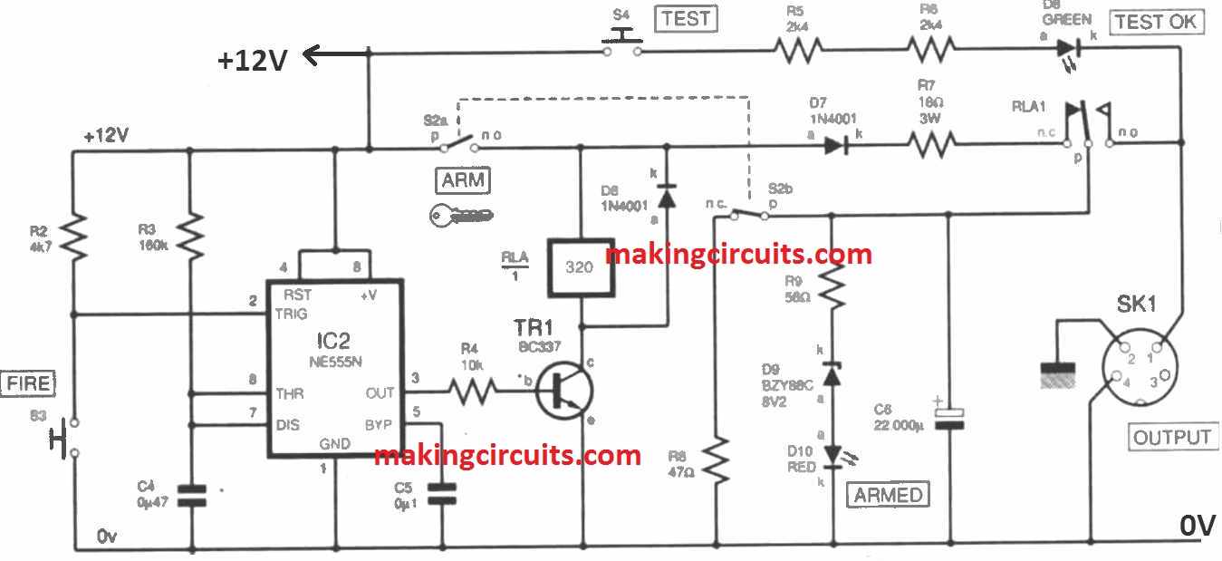
The complete schematic of a Pyrotechnic Controller circuit is depicted in Fig. 1. Commonly, around 0.2 to 0.3 Joules of energy is required to ignite the cartridge. In this part, the firing energy comes from a pulsed discharge of a high-value capacitor (C6) that is facilitated through the flash cartridge.

To make sure the component is always ready for operation, a steady power supply is constantly channeled via a standard power supply circuit that consists of transformer T1, bridge rectifiers D1 to D4, regulator IC1 and its related electronic parts. The main on/off switch S1 is made of neon-type material so that it is visible in the dark for the pyrotechnician when checking if it is powered.

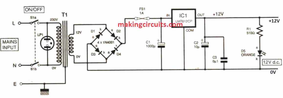
A step-down transformer that outputs a steady 12V at 1A is used for this project. Almost any type of transformer with an equivalent rating will work as a substitute. The one used in this development was obtained from an old project.
The diodes D1 to D4 provide full-wave rectification and are safeguarded by an overload fuse FS1. With a capacitance of 1,000µF, C1 works as a charge bank to supply to IC1, a normal voltage regulator.
Furthermore, the double capacitors C2 and C3 provide extra smoothing and high-frequency filtering. The reliability of the power supply can be observed by looking at LED D5 which glows a stable orange as resistor R1 limits its current.
Energy store
Capacitor C6 is the core component that stores energy in this controller. Through resistor R7 and the stalling diode, D7, the capacitor is gradually charged. The important considerations are the values of C6 and R7 which are 22,000µF and 18 ohms respectively. Furthermore, C6 must fundamentally store more energy than what is needed to trigger a common flash cartridge. Using the charge equation E = 0.5CV2, capacitor C6 stores about 1.5 Joules of energy.
The resistance of R7 is decided to shorten the charging time of C6 while restricting the maximum current from the power supply. At 18 ohms on R7, C6 charges in two seconds with a limiting current of 0.628A.
Given the flexible nature of this circuit, the value of R7 can be altered to suit the rating of the transformer. A red LED that is lit shows C6 is fully energised, and its current limited by resistor R9. Zener diode D9 acts as a monitoring component that detects the voltage at the capacitor and does not allow LED D10 to illuminate until a voltage of 10.5V is reached at C6.
Relay discharge
The prime capacitor C6 is discharged by the flash cartridge that is attached to the output socket SK1 when the relay RLA1 energises. Because of the pulsed discharge circuit design, relay RLA1 needs to be energised only for a very short interval to permit C6 to discharge. The duration that RLA1 stays energised is governed by a one-shot circuit built near a typical 555 timer, IC2.
Resistor R2 holds the trigger pin 2 of IC2 in a TRUE state, while output pin 3 is normally in the FALSE state so that the transistor TR1 is switched off. When the pushbutton switch S3 is engaged, the one-stop circuit is activated, putting pin 3 on a TRUE state and switching on TR1 and inevitably turning relay RLA on.
Resistor R3 and capacitor C4 dictate the duration of the pulse at pin 3. Normally, these values are designed to generate a pulse of 80ms, which is ample time to ignite the cartridge.
Capacitor C6 charges from the supply when the key-controlled switch S2 is turned on. The key control acts as a safety measure to inhibit the accidental deployment of an armed flash cartridge.
When the cartridge is ablaze and relay RLA1 is de-energised, capacitor C6 will recharge again. Once S2 is placed in the safe position, the closing-contact S2b will engage and allows C6 to safely discharge through resistor R8. The selected design value of R8 causes the C6 to discharge in 5 seconds.
Test circuit
As previously mentioned, the cartridge must fire when intended. The most typical reason it does not is bad wiring connections.
This controller alleviates such risk through an efficient “test” circuit that checks the continuity of the wiring to the flash cartridge. For safety reasons, a low-current LED, D8 is protected by current-limiting resistors R5 and R6 which are connected in series.
The resistors R5 and R6 are connected in series so that in the event of one them failing, an open circuit will prevent dynamic current flow to the flash cartridge, resulting in early blastoff. S4 is the toggling component for the Test switch.
Although S3 and S4 are momentary latching switches, they look different. The prime difference is visible in the type of button that is installed. S3 has round borders while S4 equips a square one. The main reason for such design choices is because of the important timing of the flash.
Since both the switches have different buttons, the pyrotechnician would be able to identify the differences by just touching them. This design idea comes in handy because almost all the time, the backstage scenario is dark and the pyrotechnician would not want to miss a cue by pressing the “Test” button instead of “Fire”.
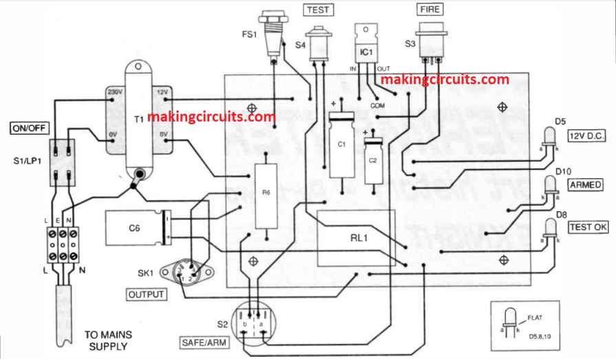
A metal case that is grounded to Earth via arrester cables accommodates the Pyrotechnic Controller circuit. The construction of the output socket SK1 consists of a metal 4-pin and made for DIN rail mountings. A complete shield is designed together with a twin cable which forms the output cable. Pin 2 of SK1 facilitates the connection between the case and the shielded cable. As a good practice, a shielded cable with a conductor area of 0.5 mm2 must be utilised to preserve the reliability and durability of the connection.
Construction
Although it might seem there are many components on the case, the development of the Pyrotechnic Controller is easy. Smaller electronic parts are mounted on a Printed Circuit Board (PCB) and this can be purchased at EPE PCB Service, code 155. Fig. 2 displays the top and bottom side views which consist of component design and whole copper track master respectively. When inspected deeply, there are three wired connections which are plugged to the circuit board.

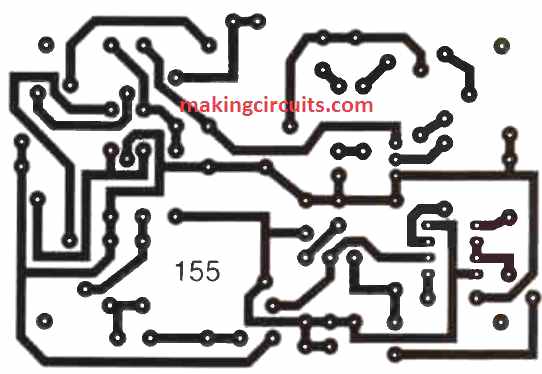


When soldering the semiconductors on the PCB, great attention and care must be upheld. Although a plug can be used for IC2, straight soldering is preferred because of its dependable connection. Since R7 is a big resistor, the electronic component should be fixed in such a way that its body is over the PCB.

Testing and operation
It is imperative that during the first test of the controller unit, a live flash cartridge MUST NOT be used. The first test is conducted to determine if the connections are secure and without any short circuits in the power supply. The rest of the test can be carried out as if operating the controller normally, but a low-rated resistor must fill in for the flash cartridge.
After removing the 1A fuse from the holder, examine for short circuits in between the 12V supply rails using a multimeter that is configured to an x10 resistance range. The measurement should be carried out across capacitors C1 and C2.
Following that, a 1A fast-blow fuse is placed on its bracket and connect a low-range resistor, typically around 4-7 ohms, to pins 1 and 4 of SK1. Then, turn the range dial on the multimeter to DC volts and measure across capacitor C6. It is critical to ensure that key-switch S2 is locked in the Safe (off) side before plugging in the controller and turning on switch S1.
When the connections are correct, the neon inside switch S1 and LED D5 must be lit. After that, press the square-shaped switch S4 (test) and LED D8 should light up.
After placing switch S2 on the “Arm” position, the Pyrotechnic Controller circuit will standby to be engaged. At this moment, capacitor C6 will instantly charge to around 12V and cause D10 to light.
Once this happens, confidently press the round switch S3 (Fire) and release it. The reading on the multimeter will drop and rise gradually as the capacitor C6 gets discharged and recharged. LED D10 will not be illuminated at first but once the voltage across capacitor C6 achieves 12V, the light comes back on.
When the tests are positive, the controller is fit and ready for live launch.
Safety
All pyrotechnic controller circuits must be handled with care because they are very dangerous. The instructions manual from the manufacturers must always be adhered to prevent unintended release of the flash cartridge. Moreover, when a cartridge is ready to be fired, there must not be a single risk of personal injury or damage to the environment.
When carefully operated within the guidelines, flash cartridges can amplify the wow-factor of any stage production. Be responsible and have fun at the show.
“Tidying up the loose cable connections using cable ties is an effective way to avoid mistakes and ensure connection integrity. To inhibit the risk of short circuits, all hot connections must be insulated at their solder connections.”