


The post widely explains a MPPT based wise solar cell phone charger circuit.

Talking about the above wise solar charger circuit, the design might be split up into three basic steps:
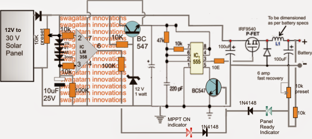
1) The mosfet based buck converter stage.
2) The IC 555 astable stage, and
3) The opamp based solar tracker MPPT stage.
The phases are created to function right here manner:
The buck converter generally includes a P-channel mosfet, a swift reply diode and an inductor. This level is insured with the intention to gain the preferred amount of stepped down voltage with maximum effectiveness, considering that loss by means of heat as well as other guidelines are minimum applying a buck topology.
The IC 555 stage is rigged to produce a frequency for the buck converter mosfet as well as as a continuing voltage regulator by means of its control pin5. The BJT at its pin5 grounds and shuts off the buck converter frequency each and every time it gets a base trigger signal either from the opamp tracker stage or from the feedback set across the buck converter output via the 10k preset.
Visiting the opamp stage, its inputs might be observed designed in such a technique that the potential at the inverting input of the IC remains a pinch greater than its non-inverting input as a result of the existence of the three 1N4148 reducing diodes.
The 10k preset is modified such that at peak voltage the sample solar voltage at pin2 is kept just below the supply voltage at pin7, this really is important since the input feed ought not to be greater than the supply voltage of the IC as per the normal guidelines and specifications of the IC.
In the above circumstance, the output pin6 of the opamp is held at zero potential on account of the shade lower potential of pin3 than pin2.
Under optimal load situations, when the load voltage spec is on par with the solar panel voltage rating, the panel immediately operates with maximum effectiveness and the opamp tracker remains dormant, in spite of this in the event an unmatched or incompatible overload load is felt, the panel voltage is likely to get pulled down with the load voltage level.
The problem is tracked at pin2 which also views a proportionate voltage drop, but the potential at pin3 remains solid and unmoved as a result of the existence of the 10uF capacitor, until the moment when the pin2 potential tends to go below the 3 diode drop set across pin3. Pin3 now starts seeing a rising potential than pin2, which swiftly offers a high at pin6 of the IC.
The above high at pin6 delivers a trigger at the base of the BC547 transistor placed across pin5 of the IC555.
This causes the astable to shut off itself and the buck output, which often offers the load ineffective restoring normalcy across the panel and the opamp tracker stage...the cycle maintains switching quickly, guaranteeing an optimized voltage for the load in addition to an optimized load for the panel so that its voltage by no means falls below its critical "knee" zone.
The inductor of the converter stage might be developed making use of 22 SWG magnet wire, with around 20 turns over any appropriate ferrite core.
The 10k preset can be utilized for changing the buck voltage to the needed levels as per the load requirements.
How to Establish the Circuit
Once built, the above described smart solar charger might be set with the following methods:
1) Usually do not hook up any load at the output.
2) Utilize an external DC (very low current) across the input of the circuit where the panel is meant to be attached in. This DC ought to be at a level around equivalent to the chosen panel peak voltage features.
3) Change the 10k preset of the opamp such that the potential at pin2 turns into somewhat less than the potential at pin7 of the IC.
4) Subsequent, change the other 10k preset such that the output from the buck converter generates a voltage just equal to the meant load voltage rating. If its a cell phone that should be charged, the voltage might be set to 5V, for a Li-ion cell it might be set to 4.2V and so on.
4) Lastly hook up a dummy load which can possess working voltage rating much lower than the input DC but higher current rating than the input DC....and verify the overall reply from the circuit.
The circuit must generate the following outcomes:
With the pin6 feed associated with pin5 BJT of the IC 555 the DC should never display a drop of more than 2V than its real magnitude.
Which means if the input DC is 15V, along with the load is 6V, the drop across the input DC might be observed not going above below 13V.
Conversely with pin6 turned off this should decrease and align in keeping with the load voltage, that is definitely if the DC is 15V and the load is 6V, the input DC might be observed reducing at 6V.
The above outcomes would certainly verify a proper and an optimal working of the offered smart solar cell phone charger circuit.
The phases has to be developed, analyzed, established step-wise, and then built-in with each other
Universal Solar Cellphone Charger Concept Explored
The following post which causes a 20 cell phone charger station utilizing solar power.
The Design:
In accordance with me, putting together the whole station making use of ready made units could well be significantly better idea rather than creating the particular circuits. This method is going to be faster, simpler and will stay away from a lot of problems which can be frequently an important part of producing techniques.
The cell phone charger necessity could be worked out by picking out and setting up 20 nos. ready made cell phone chargers and by hooking up their mains inputs in parallel to a small solar inverter.
Charging a cell phone Li-Ion battery can be extremely crucial and needs high grade smart chargers with auto shut-off abilities for charging them easily.
Processing this kind of smart charger needs a number of expertise and experience, so I will not likely suggest providing these units.
Rather than 20 nos. used cell phones might be obtained (example NOKIA1280) and can be utilized as Li-Ion battery holders cum chargers.
All mobile phones have an incorporated smart charger which charge the required battery with greatest treatment and instantly close off the method when the charging is finished. The display offers the needed info with a beep sound once the charging is done, so that's a cool way of charging the Li-Ion batteries without taking any risks.
The cellular phones can be utilized generally while they are not getting used for charging the above batteries.
The following block diagram shows the various phases which may be used for putting in 20 solar powered cellular phone station:


The first four blocks signify a regular solar electrification set up. The solar panel voltage is first designed to the preferred battery voltage by means of a solar charger/controller module.
The output from the solar module is then given to an inverter battery for charging it.
The charger/controller immediately removes the charging of the inverter battery when it's fully charged and resumes when it gets to the under charge threshold level.
The battery is utilized for traveling the inverter at any time needed.
The output of the inverter is employed for charging the offered mobile phones and the Li-Ion batteries.
20 cell phones would certainly approximately utilize 20 to 30 watt hour of power, so a 100 watt inverter would probably properly work the purpose.
A 40 AH car battery is advisable right here, which might cheerfully fulfill the 5 day autonomy demand.
The solar panel is not at all important below, a 60 watt panel owning an open circuit voltage of 30V and a short circuit current of 3 amps will likely be quite well suited for the current application.
The solar charger/controller is the only devices which might be produced at home. I have by now mentioned the kind of circuit in this post, which can be efficiently raised for the existing application (the transformer ought to be changed by the solar panel terminals).