Here we have a simple solar battery charger circuit using LM338 which is a voltage regulator IC but we use it for charging. So now, let us understand how this thing works.
Please note that, you can replace the IC LM338 with LM317 IC if your battery is rated lower than 7 Ah
Working Description
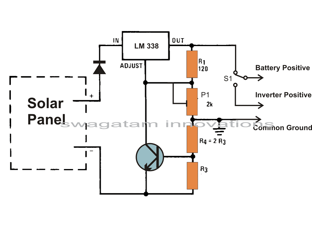
First our solar panel gives the input power, which enters LM338 at its "IN" pin. This IC will control the voltage and current so our lead-acid battery can charge safely. Now we see a diode at the output, this stops the battery from discharging back into the circuit when there is no sun.
The LM338 has an "ADJUST" pin which decides the output voltage. We connect a resistor R1 (120 ohm) and a potentiometer P1 (10K) to this pin.
So by adjusting P1 we set the charging voltage for the battery. But wait, we also need to control the current right? That is where R3 and BC547 come into play.
Constant Current Control
Now look at R3. We calculate its value using:
R3 = 0.7 / Charging Current
This means if we want 2A charging then R3 = 0.7 / 2 = 0.35 ohm. Simple.
But what does BC547 do? This transistor is like a switch. When charging current is high then voltage across R3 rises and when it reaches around 0.7V, BC547 turns ON.
This pulls the "ADJUST" pin lower, reducing the LM338’s output voltage which in turn reduces charging current. So this way, we get automatic current control.
Charging Current Display
Finally we put an ammeter in series, so we can see how much current is going into the battery. If sun is bright then current will be high, if weak then, current will drop. And that is all, now we have a solar charger that controls both voltage and current to safely charge our lead-acid battery.
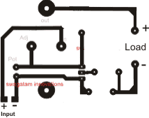
Circuit Diagram


Track side PCB Design (R4, Diode and S1 not included...R4 is actually not important and may be replaced with a jumper wire.
How to Build
Remember you need to build this solar charger properly, otherwise it may not work well. S, let us see step by step.
- Heatsink for LM338
Now first thing, LM338 will get hot when charging because it is handling high current. So we must fix it on a big aluminum heatsink, otherwise it may shut down or burn. If we see it getting too hot we need a bigger heatsink or maybe a small fan.
- Diode Selecting
Now look at the diode after LM338. It must handle the full charging current. If we plan for 5A charging then we need a diode rated for at least 6A or more. A good choice is 1N5408 (3A) for small current or 6A4 (6A) for bigger current. This diode must also be attached properly or charging will not happen.
- Wiring and Soldering
Ok, now wiring part. Since we are handling high current so the wires must be thick, especially from the solar panel to LM338 and from LM338 to the battery. Thin wires will drop voltage and charging will be slow. Also soldering must be solid, no loose connections or things will heat up.
- Potentiometer (P1) Setting
Now adjusting voltage. Before connecting the battery we turn P1 slowly and set the output to 14.2V (for a 12V lead-acid battery). We can use a multimeter at the output to check. If it is too high then battery will overcharge, if too low then charging will be weak. So this step is important.
- Testing and R3 Placement
R3 (current control resistor) must be high-wattage, at least 5W or more because it will get warm when charging. We can use multiple low-ohm resistors in parallel to get the right value. After fixing R3, we check with an ammeter to see if current is correct. If needed then we adjust R3.
- Final Connection to Battery and Charging
Once everything is set then we connect the battery last. First we check solar panel voltage then we connect the battery terminals properly (plus to plus, minus to minus). If connections are reversed, then circuit will not work or even worse, it may damage components.
So now we are ready! If built correctly then this circuit will charge the battery safely and we can monitor the current using the ammeter. Simple and effective…
Calculating Charging Current for the Battery
By choosing the resistor R3's value suitably, one may choose the charging current.
The formula may be solved as follows: 0.6/R3 = 1/10 battery AH
Adjusting the preset VR1 allows the regulator to supply the necessary charging voltage.
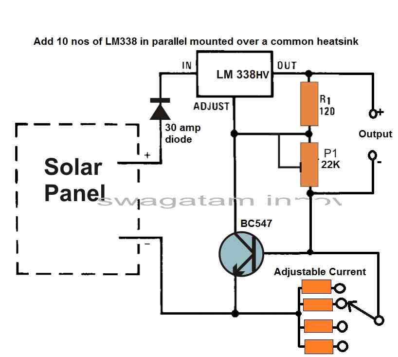
Solar Regulator with Adjustable Voltage and Current Output
The LM338 ICs are used in the high current voltage regulator circuit depicted in the accompanying image.
Several LM338 Ics are connected in parallel atop the same common heatsink to obtain the high current.
Although they are not included in the design, you might connect a minimum of eight LM338 ICs in parallel when assembling it actually.