

The post explains a simple way to calculate and implement current limiter resistor for an LED in a circuit in order to ensure that the LED never get damages due to over current, over voltage, and thermal runaway conditions.
When an LED is needed in a circuit, the current for that LED is generally fixed through a current limiting resistor. The LED could after that be turned on / off using a transistor.
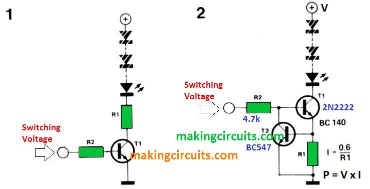
On the other hand, concept displayed in figure 1 doesn't consider any kind of changes in the source voltage.

A tiny deviation in the LED current could be highly noticeable particularly when high efficiency LEDs are employed.
The inclusion of just one single transistor can easily convert the circuit of figure 1 into a current source that can be turned on an off (for example, with TTL levels).
The circuit of figure 2 demonstrates that resistor R1 is actually relocated to the emitter of T1. When a supply voltage is given to the input of T1, this specific transistor switches ON allowing a current through R1.
Transistor T2 regulates the base current of T1 in a way that the voltage drop around R1 continues to be at 0.6 V.
How to Calculate LED Current and Resistor
The current, I, by means of the LEDs and R1 is determined through the formula I= 0.6/R1. In case, for example, R1 is 12 Ohms, the current via the LEDs is 50 mA.
Remember the dissipation of T1 is considerably greater than in the circuit of figure 1, nevertheless on the hind side, the dissipation in R1 is not really too high.