

All of us are quite acquainted with “Hello world!” basic program code in the primary stage of any programming language to understand some fundamental points. In the same way to begin with with 8051 Microcontroller, LED interfacing can be a fundamental part of Microcontroller interfacing programming.
Every Microcontroller differs in its engineering, but the interfacing principle is just about all the same for all Microcontroller. This specific course will provide you with an LED interfacing with 8051.
Interfacing is an approach, that facilitates communication across Microcontroller and the interface device. An interface can be either an Input device, or output device, or a hard disk drive, or application device.
Input Interface Devices can be anything such as a Push button switch, Keypad, Infrared sensor, Temperature sensor, gas Sensor etc. These equipment offer some information to the Microcontroller, which is known as as input data.
Output Interface Devices can be devices like an LED, LCD, Buzzer, Relay driver, DC Motor Driver, 7-Segment Display etc.
Storage Interface Devices are Used to store/ retain the data, such as, SD card, EEPROM, DataFlash, Real Time Clock, etc.


Interfacing of an LED with 8051
Interfacing includes hardware (Interface device) and Software (source code to communicate, also known as the Driver). Basically, to apply an LED in the form of an output device, IT needs to be plugged into Microcontroller port and the MC is required to be programmed internally in order to enable the LED ON or OFF or blink or dim. This program is known as the driver/firmware. The driver software could be designed employing any kind of programming language such as Assembly, C etc.
8051 Microcontroller
The 8051 Microcontroller was developed in 1980’s by Intel. Its groundwork is founded on Harvard architecture and this Microcontroller originated primarily for enabling it to be used in Embedded Systems. We have talked about earlier regarding 8051 Microcontroller History and Essentials. This is a 40 Pin PDIP (Plastic Dual Inline Package).
8051 includes an in built oscillator, nonetheless it calls for an external clock to operate it. A quartz crystal is attached between the XTAL pins of the MC. This crystal demands a couple of identical value capacitors (33pF) for producing a clock signal with the required frequency.


LED (Light Emitting Diode)
LED is a semiconductor unit employed in numerous electronics, primarily intended for signal transmission /power indication requirements. It is quite low cost and quickly accessible in a number of shape, color, and size. The LEDs can also be used for creating message display screen panels and traffic control signal lights etc.
These have 2 pins, positive and negative as demonstrated in the figure below.


The only approach to understand polarity is either to check it using a multimeter or by cautiously seeing inside the LED. The bigger ending within the led is -ve (cathode) and the smaller one is +ve (anode), that is the way we determine the polarity of the LED. A different way to identify the polarity is, joining leads, POSITIVE terminal which is longer in length compared to NEGATIVE terminal, which has a shorter length.
LED Interfacing to 8051
You will find a couple of methods that we can be applied to interface LED to the Microcontroller 8051. However the connections and programming methods will change. This post presents the details on LED interfacing with 8051 and LED pulsating code for AT89C52/ AT89C51 Microcontroller.


Notice very carefully the LED#2 interface is at forward biased since the input voltage of 5v is linked on the positive terminal of the LED, Thus here the Microcontroller pin must be at LOW level, and in the reverse order with the connections for interface#1.
The resistor is vital for all types of LED interfacing to restrict the applied current and prevent harming the LED and/or MCU.
Interface#1 will illuminate the LED, as long as the PIN value of the MC is HIGH, while current runs towards the ground.
Interface#2 will illuminate LED, as long as the PIN value of the MC is LOW, while current streams towards PIN because of its lower potential.
The circuit diagram is displayed below. An LED can be seen attached to the pin-0 of port-1.
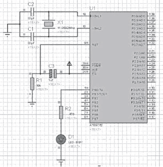

I am going to discuss the program code in more detail. A crystal with 11.0592 MHz is attached for creating the clock pulses. It is known to us that 8051 Microcontroller accomplishes an command in 12 CPU cycles, therefore this 11.0592Mhz crystal causes this 8051 to operate at 0.92 MIPS (Million of instructions per second).
In the code as shown below, the LED is understood to be the pin 0 of the port 1. Within the primary function, LED is switched
every half second. The ‘delay’ function completes null statements each time when this is implemented.
A value of 60000 (compiled applying Keil micro-vision4 software) produces around 1 seconds (delay time) null statement execution time whenever 11.0592 MHz crystal will be utilized. In this manner, LED mounted on P1.0 pin is enabled to blink with the code outlined in the following section.
CODE
#include

sbit LED= P1^0; // pin0 of port1 is named as LED

//Function declarations

void cct_init(void);

void delay(int a);

int main(void)

cct_init();

while(1)

LED=0;

delay(60000);

LED=1;

delay(60000);

void cct_init(void)

P0= 0x00;

P1= 0x00;

P2= 0x00;

P3= 0x00;

void delay (int a)

int i;

for( i=0; i
This post provides the details about how to implement LED interfacing with the 8051. This is actually the basic interfacing idea for 8051 microcontroller projects.
I really hope by studying this content you've gotten essential knowledge regarding the correct method of illuminating an LED module with the 8051. For those who have any kind of questions concerning this article or regarding the microcontroller projects, please be quick to comment below.