


The 4 LED temperature indicator circuit talked about here is very beneficial for obtaining a visual details about the condition of temperature which is certainly to be supervised.
In the circuit temperature status is shown utilizing four LEDs.
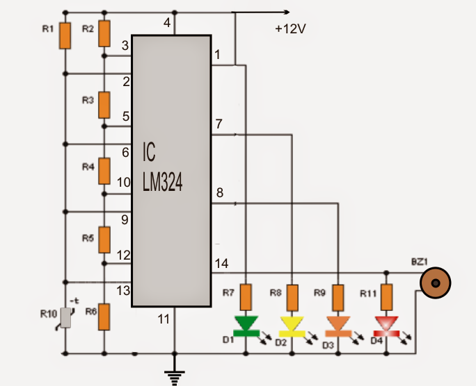
- A green LED, showing that the temperature is in the suitable level
- Two yellow LEDs are included to show that the temperature surpasses regular, along with the scenario is risky.
- A red LED alert status shows that the temperature is very high and has to be implemented immediately.
To complement the high temperature red LED warning a buzzer is included in the circuit which gives off an audible warning note to alert concerning the emergency.
The circuit is implemented employing four comparators inside the IC LM324. This really is a remarkable chip which includes four functional amplifiers comparable to 741 type together in one package.
The first phase of the diagram demonstrates a voltage divider network produced with the aid of R2, R3, R4, R5 and R6 resistors.
Here the voltages are set referenced at 2.4V, 4.8V, 7.2V, 9.6V.
All these voltages is attached straight to the non-inverting pinout (+) of the functional amplifiers which explains getting used as comparators
The upper lead of the thermistor (R10) attaches instantly with all inverting (-) terminals of the opamps.
If the subjected temperature changes, the voltage as well consequently differs at the upper pin of the thermistor.
This triggered responsive voltage is compared to the opamp comparators across their non-inverting terminals as well as in reaction to lesser voltages sends in the same way high voltage comparator output signaling the appropriate LED.
As the temperature increases, situations across the thermistor commences acquiring lower illuminating the LEDs in series.
When the lower most comparator is started, the red LED lights and triggers the "buzzer" providing an audible alert tune which might be viewed as essential if the device ought to be safeguarded.
BOM for the proposed 4 LED temperature detector circuit
- IC (integrated circuit): LM324
- Thermistor: 1 10K (R10)
- Resistors: 5 5K (R2, R3, R4, R5, R6), 1 10K, 4 220 (R7, R8, R9, R11)
- Diodes LED: 1 green, 1 yellow, 1 red
- 1 "buzzer"
Note: for the thermistor, you have to maintain the terminals long enough, to ensure that it could be terminated across the place where the temperature is in query.
