


You might have analyzed numerous transformerless power supplies within this blog and in the web, in spite of this establishing the essential mains capacitor in such circuits has constantly continued to be a problem for the many constructors.
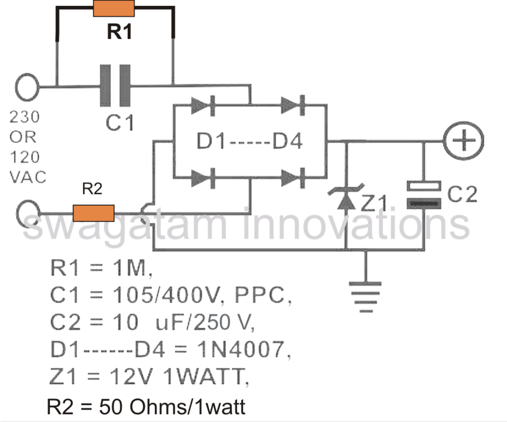
Before we understand the formula for determining and optimizing the mains capacitor in a transformerless power supply, it might be vital that you first summarize a regular transformerless power supply design. The following diagram demonstrates a classic transformerless power supply design:
![]()

Talking about the diagram, the a range of parts needed are designated with the following particular features: C1 is the nonopolar high voltage capacitor which can be launched for reducing the lethal mains current to the preferred restrictions according to the load requirement.
This element thus turns into highly crucial as a result of the designated mains current decreasing purpose. D1 to D4 are set up as a bridge rectifier network for correcting the stepped down AC from C1, to be able to make the output appropriate to any specific meant DC load. Z1 is placed for stabilizing the output to the necessary safe voltage limits.
C2 is set up to filter out any ripple in the DC and to produce a completely clean DC for the attached load. R2 might be optional but is advisable for treating a turn on surge from mains, even though ideally this component has to be restored with a NTC thermistor.
In the whole transformerless design mentioned above, C1 is a single significant component which should be dimensioned properly to ensure that the current output from it is optimized optimally according to the load requirement.
Choosing a high value capacitor for a comparatively lesser known load may well improve the chance of too much surge current getting into the load and damaging it sooner.
A correctly determined capacitor on the other hand guarantees a managed surge inrush and small dissipation sustaining sufficient safety for the linked load.
The significance of current that could be optimally convenient by means of a transformerless power supply for a specific load might be determined through the use of Ohm's law: I = V/R where I = current, V = Voltage, R = Resistance Nevertheless as we can notice, in the above formula R is an odd parameter since we are managing a capacitor as the current limiting member.
To be able to crack this we should instead obtain an approach which is able to translate the capacitor's current limiting value when it comes to Ohms or resistance unit, to ensure that the Ohm's law formula might be overcome.
To accomplish this we first discover the reactance of the capacitor which is often viewed as the resistance same as a resistor.
The formula for reactance is: Xc = 1/2(pi) fC where Xc = reactance, pi = 22/7 f = frequency C = capacitor value in Farads
The outcome received from the above formula is in Ohms and this can be instantly replace it with in our above Ohm's law.
Let's crack an illustration for knowing the achievement of the above formulas: Let's refer to how much current a 1uF capacitor can produce to a specific load:
We certainly have the following data in our hand: pi = 22/7 = 3.14 f = 50 Hz (mains AC frequency) and C= 1uF or 0.000001F
Solving the reactance equation making use of the above data gives: Xc = 1 / (2 x 3.14 x 50 x 0.000001) = 3184 ohms somewhere around Substituting this equivalent resistance value in our Ohm's law formula, we get: R = V/I or I = V/R
Considering V = 220V (since the capacitor is designed to assist the mains voltage.) We get: I = 220/3184 = 0.069 amps or 69 mA approximately
Likewise other capacitors might be determined for understanding their maximum current providing capacity or rating. The above conversation widely describes how a capacitor current might be determined in almost any appropriate circuit, especially in transformerless capacitive power supplies.