


This really is a RF jammer planned for the U.S. 800 MHz cellular phone band (870-895 MHz). This performs by providing an extreme sweeping RF carrier on the cell phone handset's performing frequency range.
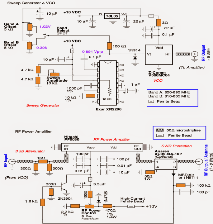
An Exar XR2206 Multi-purpose Generator should certainly serve as the triangle wave generator for offering the sweep portion of the jammer circuit. The sweep generator will definitely manage a Z-Communications V580MC04 Voltage Controlled Oscillator (VCO) to sweep between approximately 850-895 MHz at a pace of around 100 kHz.
The VCO is undoubtedly the vital component in a mobile phone jamming system. It's a tad four-terminal gadget (Vcc, RF Output, Voltage Tune, and Ground) which generates the favored low-level RF output signal with a nominal degree of inconvenience. Unluckily, VCOs created to cover the designed frequency range we might choose my not turn out to be easy to receive. Suppliers like Mini-Circuits and Z-Communications at this moment favoring instead the amateur of electronics enthusiasts, who are prepared to be able to provide their VCO products in individually directly or supply you to a local vendor.
The VCO you select should certainly involve the frequency range of the cellphone base station's downlink wavelengths (tower transmit) which might be hoped to be jammed. You usually make an attempt to jam the receiver, as a result that is why, you might prefer to jam the mobile station's (handset) receive wavelengths - which happen to be the cellphone tower's transmitting frequencies. These kinds of frequencies may very well be unique change globally, unfortunately the in general technique will remain to be the same.
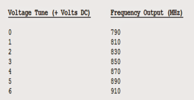
A number of 5 kohm multiturn potentiometers are set to exists a predetermined DC offset for the VCO's voltage legislation line. Precisely what this carry out is permit the sweeping triangle wave a positive DC voltage offset to support "center" the sweeping triangle wave within the needed jamming frequency spectrum. The amplitude of the triangle wave matches in harmony the frequency width of the jamming spectrum. Here's a perspective which applies a normal VCO:


In our above discussion, a normal VCO has a function of tuning between 790-910 MHz with a voltage tune from 0 to +6 VDC. This ends up to somewhere around 20 MHz of tune/volt. per volt. Which means, in the event you had the plans to "jam" the frequency ranges between 870-890 MHz, it may well necessaite a +1 volt peak-to-peak triangle wave with a DC offset of +4 volts. This can turned out to be a voltage signal sweeping between +4 and +5 VDC (referenced from ground), in addition to might sweep the VCO's RF output between 870-890 MHz. In spite of this,, in pretty much, the voltage-to-frequency mappings are not this simply critical..
A further essential little bit of the RF jammer sequence is the finish stage RF power amplifier. This could be viewed as a a stage which isolates a mini RF input signal, say as an example at +10 dBm (10 milliwatts), and enhances it approximately around +36 dBm (4 watts) and further. The convenient to get source of such amplifiers is from a few neglected analog cellphones itself. A number of unused old cellphones (Motorola, Nokia, Uniden, etc.) could possibly make use of a broadband RF power "hybrid" module which enables to create their construction much stress free and scales-down.
These particular RF module equipment are usually wideband in relation to frequeny, and is created to easily increase RF signals lying beyond their stipulated range. reinforcing the module's RF power control bias (Vapc) or Vdd voltage could in addition draw out moreover get a lot out of these, but might additionally #blank# impact the estimated life expectancy of the power module. The RF power module could need to be attached to a substantial, and well polished heatsink and may necessiatate a cooling fan on higher power amplifiers.
In an effort to carried out this project, we shall make use of a Hitachi PF0030 820-850 MHz RF power amplifier module obtained from an employed or abandoned CT-1055 Radio Shack/Nokia cellphone. Such normal appliances are installed to over 900 MHz with just a affordable reduction in gain at those upper frequency rages.. Implementing the Vdd voltage at +15 to +17 VDC could very well just a little increase the obtainable RF power output. I've pulled these to attain up to 10+ watts output under adequately layed out and fitted with a huge heatsink, however it's typically not consuming the risky scenario. Press upon keeping the optimal RF output power around 5 to 8 watts.
An inexpensive amount broadband RF power hybrid boards seldom make full use of exceeding +13 dBm (20 mW) of RF input to run as designed to be.. It might be quite right being powerred staright from the VCO's RF output not desiring any extra RF pre-amplification stage. Enhancing the RF input power could possibly only tend to influence the life expectancy of the power module and likely yield a nominal stress on the output gain.
The critical area of any radio strategy could possibly be the antenna. Throw favorable amount of money on the antenna part (and coaxial cable), and you will definitely minimal headaches on your way. Count on a coathanger and a handful of alligator clips and you may be looking to make contact with me an incredible number of instances a day complaining that it doesn't work.
On the other hand the valuable thing is, you could possibly well look out a fairly good antenna from (possibly) junked analog cellphone. Those magnetic or trunk fitted antennas grow to be suitable the best. Glass-mount antennas or some thing like that "stick-on" are traditionally a nuisance. Directional gain (Yagi) antennas may be made an effort to enrich the jammer's working range, nevertheless for just in the area the antenna is aimed. High-gain, omni-directional antennas could be taken into consideration quite effective for many of us RF jamming implementations. For homebrew prototypes, you might consider scaling down (or up) 900 MHz band amateur radio band antennas.
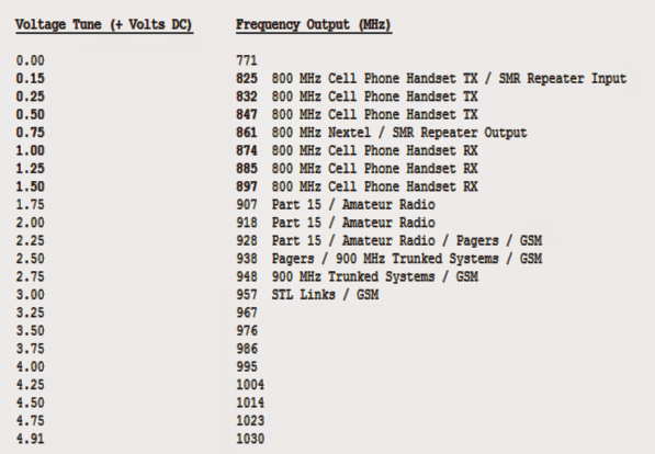
Below presented is the voltage-to-frequency mapping of Z-Comm V580MC04 VCO. The RF output power was around +8 dBm over the full frequency spectrum.

The following picture reveals a general idea of an old Radio Shack CT-1055 (Cat No. 17-1007A) 800 MHz band analog cellular phone.
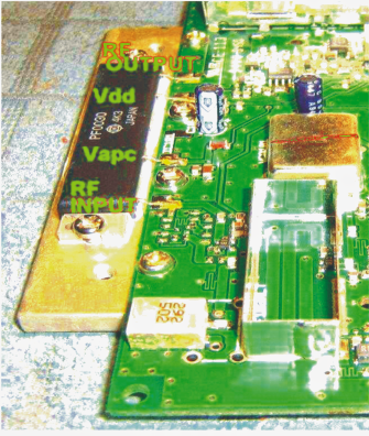

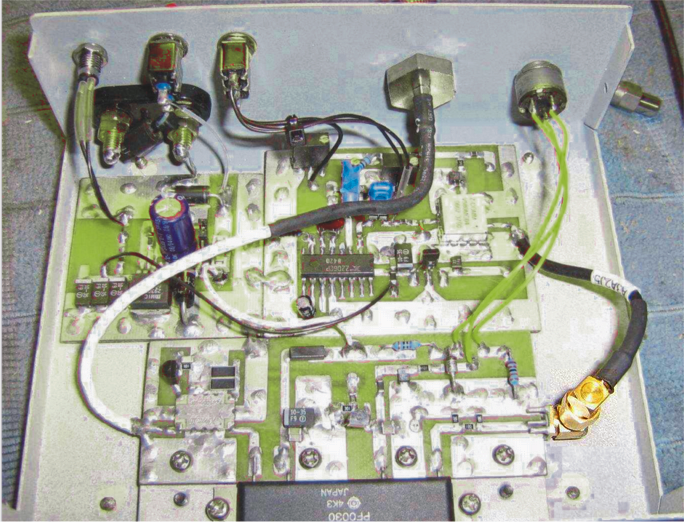
You will notice the existence of the Hitachi PF0030 RF power amplifier IC module fitted over a heatsink, and adequate heatsink compound getting used concerning the device and the heatsink. In the talked about prototype the complete IC together with the heatsink was salvaged.
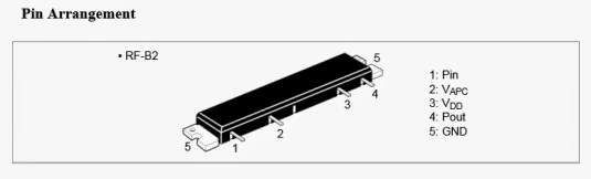
If you fail to happen to obtain such an alanogue cellphone circuit with you, you might purchase it brand new from the market, the pinout particulars of the same might be demonstrated below:

The following concept represents an overview of the complete 800 MHz Cellular Phone Jammer unit

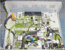
An alternate of the above could be experienced below:

Comprehensive circuit diagram of the above spelled out cellphone jammer:

10V regulated power supply for the above cellphone jammer stages

