


The circuit understands and registers the temperature distinction between two sensors and causes a relay when the temperature is not the same on these kinds of differently installed sensors.
It'll also assist you to sense a distinction in temperature, despite the fact that the temperature sensing devices may be set are discretely, employing a potentiometer.
Operational information of the offered differential temperature controller circuit.
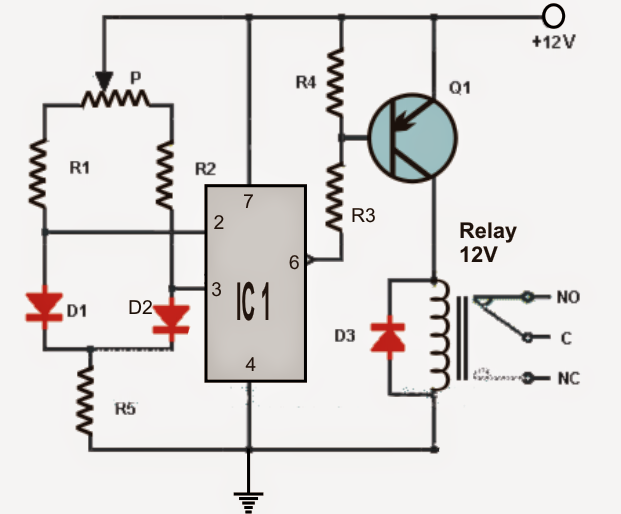
To put into action the sensing abilities a handful of normal "garden" diodes are employed as temperature sensors (D1 and D2).
As the anodes of both the diodes are associated with the inputs of an opamp it actually works such as a comparator, designed to sense any kind of temperature difference to trigger it to output a low voltage.
These kinds of diodes needs to be located over two distant wanted locations across which the temperatures could be forced to be compared. The sensors are designed for detecting even the smallest amount temperature variation across each other.
- If the diode D1 is positioned in a questionable place where the temperature fairly reduces, the op amp offers an output low and stimulates the relay by way of the via the transistor Q1. The transistor are useful to activate a heating system or equivalent with an objective of rebuilding the decrease in the temperature..
- Likewise if the diode D2 is located across a susceptible premise to detect a boost in temperature, the op amp delivers an output low again turning on the relay by way of the transistor Q1. In this particular application the transistor/relay might be employed for turning on a cooler system or a fan.
In an event when the temperature of the two diodes are restored to equal temperatures, the relay is deactivated.
Thus making it listed that the inclusion of the potentiometer is to modify the sensing levels of the circuit relating to the user selection.
Note: The circuit could very well be powered by 9V battery. The relay really should be rated at the same voltage as the supply.
List of components for the above differential temperature detector circuit:
- IC1: operational amplifier 741.
- Q1: PNP BC557
- R1 = R2: 4.7K
- R3 = R4: 1.2K
- R5: 2.7K
- P: 100K pot
- D1 = D2 = D3: diode 1N4001
- RL1: 12V relay.
