In this specific article we figure out how to produce an LED cricket stump for facilitating umpires declare a simple OUT, NOT-OUT decisions.
You are usually observing these kind of incredible cricket stumps in the regular 2015 ICC world cup cricket matches, which may be noticed dazzle or glow brightly as rapidly the ball touches any one of the stumps.
It certainly is developed by an Australian person known as Bronte EcKermann and developed by South Australian maker Zing International.
It is usually asserted that the expense of these kinds of stumps could be up to US$ 40,000 for each set, gosh!. The circuit of these kinds of LED stumps is presumed to be composing of all kinds of sophisticated design applying microcontrollers.
In the following article we shall discover how almost every circuits is generally developed employing common equipment at lesser than $5 and yet be as effective as the original LED stump specs.
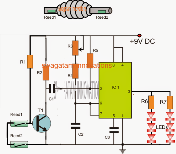
The first diagram below reveals a circuit which might be utilized inside the bails, the thought could be defined listed below:
The IC1 that may be an IC 555 is designed as a monostable whereby R3 and C2 as well as R4 determines the ON time of the LEDs.
An NPN transistor T1 can be watched along with pin2 trigger input of the IC, whose base is rigged with a number of reed switches in sequence.
The thought is straightforward: The complete circuit really should be fitted inside each of the bails with the reed switches enclosed inside the end tubes of the bails. In addition, an everlasting magnet has to be attached at the upper ends of the stumps in order that the reed switches continue to be closed for assuming these are definitely conducted over the stumps.
The figure above displays how the magnets inside the stumps really should be inserted and deployed for the bails to reply these.
As far as the bails are retained over the stumps, the reed switches continue to be closed off providing a shut OFF T1. In spite of this the occasion the bail is totally dislodged from the slots, enables the reed switches to open and activate T1 which inturn activates the monostable enlightening the LEDs for a time period as determined by R3/R4/C2. The LEDs stay turn off until these are again installed over the stumps for a repetition.
That handles the bail circuitry, really effortless.... isn't that?
In the above diagram you can easliy also understand LDRs being installed right at the top of the stumps just under small apertures that my be drilled on top surfaces of the stumps.
These kinds of LDRs grow to be come across the ambient external light the occasion the bails are dislodged from the slots. considering that these kinds of LDrs ought to be built-in with sets of similar monostables inside the stumps, the function turns out to be liable for enlightening the LEDs linked on the stumps, hence the complete system consisting of the stumps as well as the bails grow to be synchronized delivering a simple phase of the procedures.
The following circuit displays how the circuit inside the stumps really should be designed for utilizing the LED stump circuit functions.
In the diagram we can manage to observe the integration techniques of the LDRs with a 555 IC based monostable.
Assuming that the bails are held over the stumps, the ambient light stay blocked from the LDRs which continues T1 shut OFF. but the while the bails are thrown of the stumps, the LDRs emerge as connected to the ambient light making it possible for T1 to acquire a biasing voltage which usually generates the monostable so that the LEDs are activated for the set time frame mounted by the applicable components.
The LEDs shut of after the set time has expired until the bails are relocated over the stumps for another series.
Parts List for the above discussed LED cricket stump circuit
R1 = 220K
R2, R4, R5 = 10k
R6, R7 = 220 ohms
R3 = 1M preset
C1 = 0.22uF
C2 = 100uF/16V
C3 = 0.01uF
T1 = BC547
IC1 = NE555
