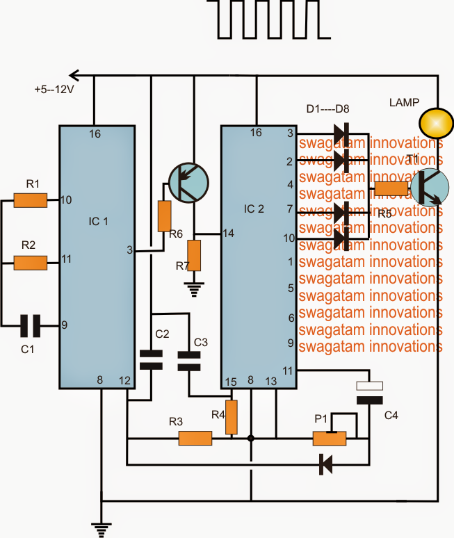
The submit features a very simple morse code lamp flasher circuit which can be chosen for model lighthouse signalling products.
Parts list for the morse code lamp for lighthouse application
R1 = TO BE CALCULATED
R2, R3, R4, R6, R7 = 1M
R5 = 1K
P1 = 100K PRESET
C1, C2, C3 = 0.22uF
C4 = 10uF/25V
D1---D8 = 1N4148
T1 = 2N2222
T2 = BC557
IC1 = 4060
IC2 = 4017
The projected morse code light house lamp may perhaps be demonstrated in the above diagram. The operation can be conceived with the following points:
IC1 4060 is set as a clock generator at certain predetermined rate by effectively choosing the value of R1. For utilizing the stipulated sequence rate, this certainly will be at the rate of 1/2 seconds at pin3 of the IC
The IC 4017 is wired in its normal sequential decade counter mode where its output pins react with a temporary high with each clock carried out at its pin14.
When the circuit is turned on, capacitors C2, C3 reset the two ICs such that IC1 starts counting from zero and a logic low at its pin3, while IC2 also does the same by keeping its first pin3 high.
With pin3 high at the beginning, T1 is activated which often switches ON the lamp.
After 1/2 second, pin3 of IC2 goes high, switching OFF T2, this generates no impact on pin14 as it gets grounded via R7, pin3 remains to be ON until another 1/2 second.
Throughout the next low from IC1, T2 gets turned on and toggles pin14 of IC2 which causes IC2 to shift its pin3 high to pin2.
Seeing that pin2 is furthermore associated with T1, the lamp happens to be ON for another 1/2 + 1/2 second after which, the sequence is shifted to pin4 of IC2 (not shown). Considering that pin4 is not linked with T1, the lamp has become turned off until another 1/2 + 1/2 second that is for complete 1 second.
Throughout the succeeding next 1/2+1/2+1/2+1/2 periods, the high jumps from the previously listed pinouts to across pin7/10 turning on the lamp one more time for 2 seconds.
As soon as the above valuable time is elapsed, the high is now transferred across pins1,5,6,9,11. Pins1,5,6,9 together implement a delay of 4 seconds, nevertheless since this stage will need to have a delay of 7 seconds according to the request, P1 ought to be modified such that when the high shows up at this pinout, the resetting of IC1 takes place for approximately 3 seconds which plays a role in the total of 7 seconds.
After this the series is flipped back to pin3 of IC2 for repeating the course as per the above stipulated morse code rate.
