


This circuit will warn you the moment there's a power failure or an interruption in the mains. In some specific situations it might be crucial to understand whether the mains that powers some appropriate system or circuit is missing.
How the power failure alarm functions
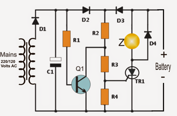
This suggested circuit is hooked up to the power mains via the transformer T1. The AC voltage is improved by the diode D1 and is filtered by C1.
Provided that there is certainly a voltage level existing at the anode of D2 (around 12 volts), transistor Q1 has the capacity to perform sustaining a negligible voltage at the gate of the SCR (TR1). Consequently the SCR struggles to get activated, making sure no triggers and no alarm tones.
It could be observed that the SCR is completely linked to a 9 volt PP3 battery.
In an event of a mains failure, the voltage from the transformer vanishes, the transistor Q1 is immediately cut-off, diode D2 makes sure that no current has the capacity to achieve Q1 base from the battery power. Also, The battery forward biases diode D3 and a current flows by means of R2, R3 and R4 resistors.
This circumstance lifts the voltage level at the gate of TR1, starting the SCR along with the connected buzzer that warns of the circumstance or the lack of mains voltage.
The instance the power comes back, the signal error message is not going to go away simply because the thyristor carries itself in latched condition on account of its inherent characteristics (with DC supply SCRs as soon as activated remain latched permanently), despite the fact that its gate now is offered with a zero voltage.
To be able to cut of the alarm and restore the condition, it might be merely essential to turn off the battery supply momentarily by means of a switch (not demonstrated in the diagram) installed in series with the 9 volt battery or in series with the thyristor anode or cathode.
Note: The buzzer might be modified by a relay for allowing a visual warning or both.


Power Interruption Alarm Circuit
Bill Of Materials for the offered mains failure alarm circuit
- 1 resistor R1 = 12K
- 1 resistor R2 = 2.7K
- 2 resistors: R3 = R4 = 1K
- 1 NPN: BC547
- 1 470 uF/25V
- Four semiconductor diodes: D1 = D2 = D3 = D4 = 1N4007
- 1 Thyristor TR1: C106Y1 (NTE5452)
- One transformer 120/240 VAC to 9 VAC or more than 500 mA
- 1 buzzer 6 or 9 volts
- 1 PP3 9 volt battery.