


This shown circuit alarm updates you after some time at any time your refrigerator door is left open.
This fridge door open alarm circuit turns into easy to carry, simply because in the event the door is left as a result of carelessness might cause tremendous increase in the consumption and influence the lifespan of the fridge.
Circuit procedure
This circuit utilizes a photosensor LDR for detecting whether the door is open, or not. At any time the sensor is lit up by the light being deducted from within the refrigerator, the circuit starts giving off an irregular sound to warn you and provide the circumstance to your thoughts.
And the moment the door is closed, and the fridge light goes off, the circuit and the alarm shuts off and prevents giving off the sound.
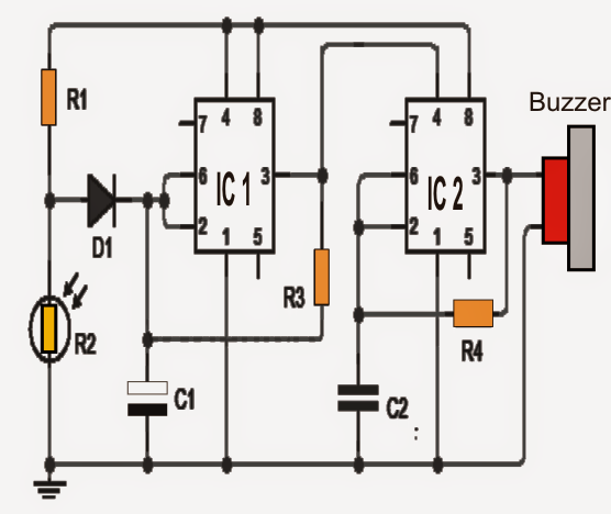
For performing the whole procedure a few timers ICs 555 are associated as displayed in Figure.
When the LDR is not presented to light the voltage on pin 2 (trigger) of the first IC 555 remains higher and its output (pin 3) is presented low. Because of this the second IC 555 is provided inhibited (low voltage level on pin 4) and the alarm is not permitted to switch on.
When the LDR encounters an illumination (door is opened), the voltage level on pin 2 of the first 555 gets low leading to the output (pin 3) to oscillate (square wave).
Throughout the oscillation when output of the first 555 is at high level allows the second 555 to get activated which also starts oscillating in tune with the first but at a more significant frequency.
A buzzer which might be observed associated with the output of IC2 now starts buzzing and alarming.
The fridge door alarm circuit utilizes a PP3 9 volt battery, and ought to be located as close as it can be to the inner light of the refrigerator.
The circuit ought to be stored inside a box that could be waterproof and sealed to avoid moisture from influencing its performance.
Refrigerator Door Open Alarm Circuit

Parts list of the refrigerator door open alarm circuit
IC1 - IC2: 2 Timer 555
C1: 1uf 25V
C2: 100nF
R1: 10K 1 / 4W
R2: LDR (photoresistor)
R3: 2.2M 1 / 4W
R4: 1M 1 / 4W
D1:1N4148
Buzzer: Piezo type DC
Another Simple Fridge Door Warning
The next fridge door security alarm is designed to inform you whether the fridge door has been closed properly or not through an alarm sound.
As all of us realize, it is crucial that doors of refrigerators and freezers remain closed most of the time.


Whenever the door of the fridge, or freezer, which is protected is pulled open, the fridge light illuminates the LDR: the circuit then gets activated and a forewarning sound is triggered until the door is shut again.
The fridge door alarm circuit could also be used to keep an eye on some other entrances (for example, to stop heat loss, or as a safety measure against a fire hazard. However due to the background light it is certainly very difficult to use an LDR.
This could for that reason be substituted with a microswitch; whereby the alarm will switch ON as soon as the switch is pressed. Be aware that this calls for a switch that closes whenever the door is opened up.
A wait of approximately 10 s between the opening of the door and the activating the alarm is offered by the time constant R3C4. In case quicker response of the circuit is essential, the value of R3 could be decreased to 220 k. At the instant the limit of NI is surpassed, the gate begins to oscillate at a frequency rate of a few kilohertz.
Each resultant output rectangular pulse at pin 3 of inverter N2 sets off the oscillator N3 which creates pulse trains whose frequency has a value of a few kilohertz. The pulse trains are applied to inverter N4 which triggers the piezo buzzer to produce a tone.
Without having N2, oscillator Na would remain switched ON continually while N1 is not being activated: the output of N1 would in that case be high, and the logic 1 at pin 8 of N3 would result in the oscillator to operate.
Inverter N4 helps to amplify the output from the buzzer. If the buzzer would directly be hooked up between the output of N3 and earth, the diaphragm would hardly vibrate from its relaxation position to one side.
By attaching the alarm buzzer through an inverter, its polarity is continually changed which leads to a doubling of the alternating voltage across it. Preset P2 gives you additional facility to adjust the volume by tweaking N3 to the resonant frequency of the buzzer.
Preset P1 decides the detection level of the alarm: the lower value reduces the cuircuit sensitivity and vice versa.
The alarm can be virtually quickly built on the printed circuit board demonstrated in figure below. Current usage in the idle condition is in the region of 0.5 mA and while the alarm sounds, it is approximately 4 mA

