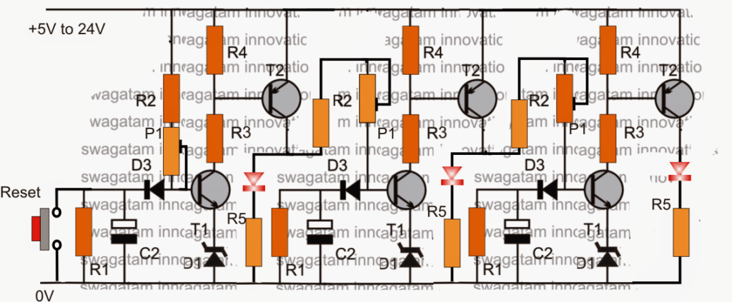
Within this publish we figure out how to create a basic sequential delay timer generator circuit that are available for obtaining a sequential initiating of a linked load, or may be basically utilized similar to a sequential LED bar graph impact generator, making use of only transistors.
The Design
The offered 2 LED sequential delay timer circuit design could be observed above, it may be also employed as a transistor LED sequential bar graph generator circuit.
I demonstrated 3 delay timer stages rather than two here, in spite of this a variety of stages could be integrated according to the application specifications.
Right here as soon as the circuit is operated, the LEDs are meant to turn on in series one after the other at a specific rate based upon the values of the appropriate RC parts which can be discretely variable, and might be set separately every one of the sequential phases..
Fundamentally, the circuit is created by configuring a group of two-transistor (T1 and T2) delay ON timer levels.
At first when power is turned on all the LEDs or the attached loads remains turned OFF
Very first the extreme left C2 starts charging gradually, and after a fixed time as set by the values of C2, R2, P1 and D1, T1 is activated ON, with T1 ON, T2 also switches ON and the first LED from left switches ON.
With the above activity T2 collector at the same time gives a charging voltage for the center delay timer's C2, which yet again repeats the cycle exactly the same as sated above.
As a result of this the center LED illuminates, and its T2 provides the signal to the right hand side delay timer phase, which experiences an equivalent stage lighting the third LED in the range.
The circumstance now continues latched with all the LEDs lighted until the "reset" switch is pushed for some instances and unveiled.
The pushing of the reset button allows the LeDs to shut off gradually in the overcome order in sequence.
In the event where the circuit is needed to function instantly similar to an LED chaser circuit, in which the LEDs need to cycle consequently producing an incrementing bar graph type series, and a reverse bar graph shutting off consequence, the following proven design may be integrated for the same.
In the above process, T3 is at first activated when the circuit is very first powered. Once the last LED is lit, T3 is compelled to close off as a result of optimistic potential from the collector of the extreme right hand side T2 transistor. The LEDs currently start shutting one after the other with a time delay as based on the value of R1s.
For situations where the LEDs need to turn off all of a sudden or immediately, the above layout could be altered in accordance with the following diagram:
As could be noticed, in the above diagram, the moment the last LED is lit, T3 is furthermore turned ON, and it pushes all the timing capacitor to turn off instantly or suddenly.
When this occurs all the LEDs shut off, and T3 subsequently is shut OFF to ensure that the cycle is permitted to do again as just stated.
Parts List
R1 = 610K (can be adjustable)
R2 = 2k2
R3, R6 = 10K
R4, R5 = 1K
P1 = 1M pot
D1 = 3V zener diode
D2 = 1N4007
D3 = 1N4148
T1,T3 = BC547
T2 = BC557
C2 = 33uF/25V (adjustable)
