An efficient solar panel MPPT charger circuit may be developed utilizing a few 555 ICs and a few other linear parts. Let's learn the methods.
An MPPT or Maximum Power Point Tracker for solar panels is an approach which allows deriving highest offered current from a solar panel during the day without upsetting its stipulated voltage, thus enabling best effectiveness from the panel.
Naturally we all understand, getting largest performance from any type of power supply turns into possible if the process does not include shunting the power supply voltage, which means we would like to obtain the specific needed lower level of voltage, and optimum current for the load which is being controlled without troubling the source voltage level, and without producing heat.
For a moment, a concerned MPPT ought to permit its output with highest essential current, any lower level of essential voltage yet ensuring the voltage level across the panel remains unchanged.
One technique which happens to be talked about right here includes PWM approach which can be among the optimum techniques to time frame.
We ought to be grateful to this little genius known as the IC 555 helping to make all hard ideas appear really easy.
In this particular idea too we implement, and greatly rely on several IC 555s for applying the MPPT impact.
Taking a look at the given solar mppt circuit making use of IC555 we observe that the whole design is essentially put into two levels.
The upper voltage regulator stage and the lower PWM generator stage.
The upper stage contains a p-channel mosfet which can be placed as a switch and replies to the used PWM info at its gate.
The lower stage is a PWM generator stage. A few 555 ICs are set up for the offered actions.
IC1 is liable for creating the needed square waves which happens to be dealt with by the continuous current triangle wave generator consisting T1 and the connected elements.
This triangular wave is used on IC2 for working into the needed PWMs.
In spite of this the PWM spacing from IC2 is determined by the voltage level at its pin#5, which can be resulting from a resistive network across the panel via the 1K resistor and the 10K preset.
The voltage between this network is instantly proportional to the various panel volts.
Throughout peak voltages the PWMs turn out to be broader and vice versa.
The above PWMs are placed on the mosfet gate which performs and offers the required voltage to the linked battery.
As mentioned earlier, throughout peak sunshine the panel produces higher level of voltage, higher voltage signifies IC2 producing larger PWMs, which often maintains the mosfe switched OFF for for a longer time periods or turned on for comparatively shorter periods, in accordance with an average voltage value that will be merely around 14.4V across the battery terminals.
When the sun shine degenerates, the PWMs get correspondingly narrowly spaced permitting the mosfet to perform much more that the average current and voltage across the battery is likely to continue to be at the optimal values.
The 10K preset ought to be modified to find around 14.4V across the output terminals under bright sunshine.
The outcomes might be checked under different sun light problems.
The suggested MPPT circuit guarantees a sturdy charging of the battery, without disturbing or shunting the panel voltage which also causes reduced heat generation.
Note: The attached soar panel will be able to produce 50% more voltage than the attached battery at peak sunshine. The current needs to be 1/5th of the battery AH rating.

An improved version of the above design utilizing buck converter may be seen in this post.
How to Set up the Circuit
It might be completed in the following way:
At first keep S1 turned OFF.
Show the panel to peak sunshine, and regulate the preset to get the essential optimal charging voltage across the mosfet drain diode output and ground.
The circuit is ready right now.
As soon as this is achieved, turn on S1, the battery will begin obtaining charged in the MPPT mode.
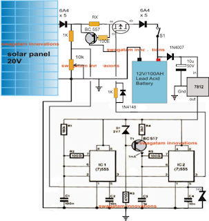
Attaching a Current Control Characteristic
A careful research of the above circuit reveals that as the mosfet makes an effort to provide the dropping panel voltage level, it permits the battery to obtain more current from the panel, which impacts the panel voltage reducing it additional down activating a run-away circumstance, this might be totally against the MPPT law.
A current control feature as demonstrated below diagram looks after this issue and prevents the battery from attracting too much current beyond the specific limitations. Consequently assists in keeping the panel voltage unaltered.
RX which happens to be the current restraining resistor could be determined with the aid of the following formula:
RX = 0.6/I, where I is the stipulated minimum charging current for the linked battery
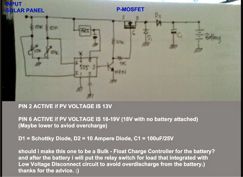
A crude but less complicated version of the above described design might be constructed making use of pin2 and pin6 threshold detection of the IC555, the total diagram could be observed below: