In this article I am going to share my journey of building a combined circuit module that functions as both a digital voltmeter and a digital ammeter.
This nifty little device is designed for measuring DC volts and current across various ranges all in a digital format.
Introduction
So let us dive into the world of electrical parameters specifically voltage and current which are pretty much the bread and butter of electronics and electronic engineers like myself.
Honestly any electronic circuit just feels incomplete without having the right supply of voltage and current levels.
Now when we talk about our mains AC supply we are dealing with an alternating voltage that typically sits at around 220 V.
To make these voltages usable in electronic circuits we often incorporate DC power adapters that effectively step down those mains AC voltages into something more manageable.
However here is the catch most power supplies out there do not come with built-in power monitoring systems.
This means they lack voltage or current meters that would display the relevant magnitudes for us.
Instead what I usually see in commercial power supplies are simple displays like calibrated dials or those ordinary moving coil type meters.
Sure these might work fine for basic applications where precision is not critical but when it comes to more complex and sensitive electronic operations or troubleshooting having a high-end monitoring system becomes absolutely essential.
That is where a digital voltmeter and ammeter come into play.
These tools are incredibly handy for monitoring voltages and currents accurately while ensuring that safety parameters are not compromised.
In this article I am excited to explain an interesting and accurate digital voltmeter and ammeter circuit that I found can be easily built at home.
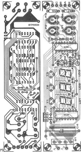
However I should note that for achieving accuracy and perfection having a well-designed PCB is definitely a must.
Circuit Operation
Now let us talk about how this circuit operates.
The magic happens with the help of ICs 3161 and 3162 which process the input voltage and current levels we are measuring.
The processed information can be read directly on three 7-segment common anode display modules which is pretty neat right?
For this circuit to function properly it requires a well-regulated 5-volt power supply section.
Trust me when I say this is crucial because the ICs strictly need that 5-volt supply to operate correctly.
To ensure that the displays shine brightly for easy reading they are powered by individual transistors.
I have used BC640 transistors in my setup but you could also experiment with alternatives like 8550 or 187 transistors if you would like.
The proposed digital voltmeter and ammeter circuit module can effectively be used alongside a power supply to indicate both voltage and current consumption by whatever load is connected through those attached modules.
If you take a look at the circuit diagram below you will see that the 3-digit digital display module is built using the CA 3162 IC which serves as an analogue-to-digital converter.
Complementing it is the CA 3161 IC functioning as a BCD to 7-segment decoder IC both of which are manufactured by RCA.

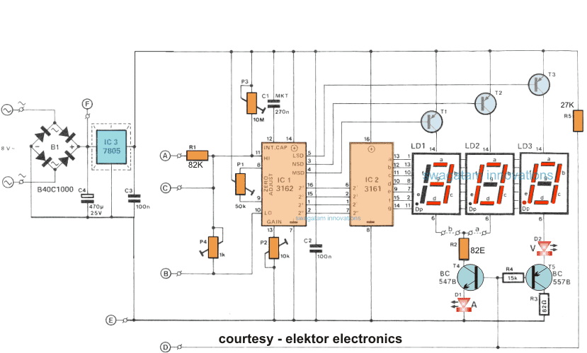
Let me explain how the displays work in this circuit.
The 7-segment displays that I am using are of the common anode type and they are connected across the transistor drivers labeled T1 to T3.
These connections allow the displays to indicate the relevant readings that we are interested in.
One really cool feature of this circuit is that it includes a facility for selecting the decimal point according to the specifications of the load and the range we are working with.
For instance when I look at the voltage readouts I can see that when the decimal point lights up at LD3 it signifies that I am in the 100mV range.
When it comes to measuring current this selection facility gives me the ability to choose between a couple of ranges.
I can select from one range which goes from 0 to 9.
99 amps and another range which goes from 0 to 0.
999 amps by using the link labeled b.
This means that depending on what I need for my measurements the current sensing resistor is either a 0.
1 ohm resistor or a 1 ohm resistor as illustrated in the diagram below

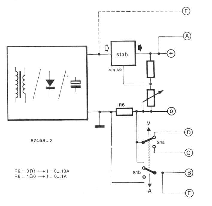
Ensuring Proper Resistor Placement and Functionality
To make sure that R6 does not have any effect on the output voltage I need to position this resistor before the voltage divider network.
This network is responsible for controlling the output voltage so it is crucial that R6 is placed correctly.
I use S1 which is a DPDT switch to select either the voltage or the current reading based on my preference.
When I set this switch for measuring voltage P4 along with R1 provides an attenuation of around 100 for the input voltage that I am feeding into the circuit.
Additionally at point D I enable a lower voltage level which allows the decimal point on the LS module to illuminate and the figure "V" becomes brightly lit up.
When I hold the selection switch towards the Amp range the voltage drop that I acquire across the sensing resistor is applied directly to the Hi-Low input points of IC1 which is the DAC module.
The significantly low value of the sensing resistors ensures that there is a negligible effect on the outcome of the voltage divider.
Adjustment Ranges for the Displays
In this proposed digital voltmeter ammeter circuit module I have included four adjustment ranges.
P1 is used for nulling the current range.
P2 is for enabling full scale calibration of the current range.
P3 is for nulling the voltage range.
P4 is for enabling full scale calibration of the voltage range.
I recommend adjusting these presets in the order listed above because P1 and P3 are specifically used to correctly nullify their respective parameters within the module.
P1 helps me compensate for the regulator operating quiescent current consumption value which results in a minor negative deviation across their voltage range.
This negative deviation is effectively compensated by P3.
The voltage and current display module operates using an unregulated supply from my supply source without any issues as long as it does not exceed 35V maximum.
I take note of points E and F in the second figure above because in this case I can eliminate bridge rectifier B1.
Now I can design this system in such a way that it can acquire concurrent voltage and current readings.
However it should be recognized that each time both devices are powered from the same source the current sensing resistor is short-circuited by means of ground links.
There are basically two methods to tackle this issue.
The first method involves hooking up the voltage module from a different source while using my current module from what I refer to as the "host" supply.
The second method is a bit more elegant and requires hardwiring areas E to the left side of the current sensing resistor.
You do need to be aware though that in this case our highest possible voltage reading becomes 20.
0 V since R6 drops 1 V maximum.
This happens because the voltage at pin 11 usually will not exceed 1.
2 V.
If I want to display larger voltages I can do so by selecting a lower current quality meaning R6 becomes 0R1.
For example if R6 drops 0.
5V at a current usage of 5 A then I ensure that 1.
2 - 0.
5 equals 0.
7V remains available for my voltage reading.
The maximum display in that case would then be calculated as 100 times 0.
7 which equals 70 V.
Just as before these kinds of complications only arise when I use a couple of these units all powered from one supply.
PCB design for making the above discussed modules