

In this post we discuss a circuit idea which will protect an empty house from potential burglars by switching the home lights ON OFF randomly, creating an effect that it is occupied by actual residents of the house.
Burglars are most likely to strike a house when its residents are out on a vacation, leaving the house unattended. One of the things they notice first is that the house remains dark for a long time, maybe even days, meaning it is empty enough for his convenience.
You can throw off any scheming burglar using the circuit discussed here. This anti-burglar light turns on and off the lights in your home randomly after it gets dark. They keep the lights on 1-5 hours to make it seem like the place is occupied.
How it Works

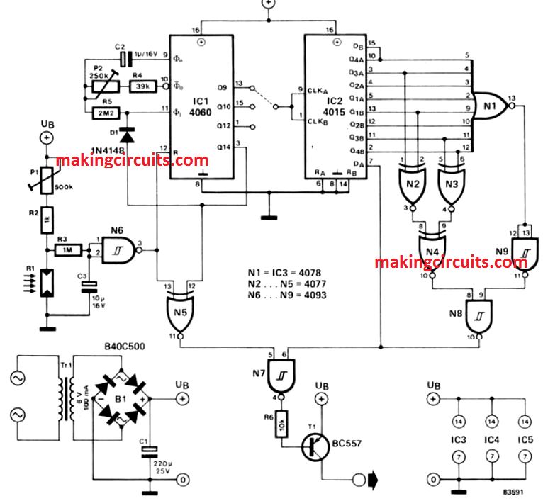
Referring to the circuit diagram above, when it gets dark, the LDR or light-dependent resistor R1 increases in resistance. This causes the gate N6 to produce an output of logical state ‘0’. You can set the point when this should happen using P1. The reset input pin 12 in the counter IC1 is also ‘0’ at this point when IC1 begins counting.
The frequency of the internal clock oscillator in the counter depends on the C2 capacitor, P2 potentiometer and the R4 resistor.
P2 helps keep the frequency within the range of 0.9 and 4.5 Hz. N5 will start having an output of ‘1’ from when IC1 starts counting. But until N8 also shows a ‘1’ state, the output of N7 remains unchanged and consequently, that of T1 too. This will be effected by IC2 and the gates it consists of.
IC1 it feeds clock pulses to IC2 as it counts, which come from the outputs of Q9, Q10 or Q12, ie, pins 13, 15 or 1, of IC1.
The result is the formation of a quasi-random generator using the outputs of IC2 and the gates N1 to N4 plus N8 and N9. This controls the T1 transistor through the N7 gate and randomly switch the house lights on and off in a manner that will make burglars infer that someone is home.
As a result, several things will happen now. The internal clock oscillator will be stopped through the diode D1, which, in turn, will keep Q14 in the ‘1’ state. The lights of the house will be switched off due to the N7 gate being suppressed.
Thus, there will be no disturbance and the process will resume next evening. The burglar, of course, will have left, discouraged. It is also quite easy to calibrate the random generator.
P1 decides the sensitivity of R1, ie, or the intensity of light that is the threshold for N6 to switch. P2 sets the full operation time for IC2 and the ‘random’ pattern depends upon which Q outputs of IC1 are used for clocking IC2.
It is a taken that IC2 and the gates associated with it need not be used if the random generator is not needed. But you should not miss connecting to the positive supply line the pin 6 of N7.
You can connect a relay to T1 for getting the lighting in the house to switch on and off. But you should make sure that the relay does not consume greater than 50 mA of current for this. If the relay ends up drawing more current than that, then you will have to get the mains transformer and T1 uprated.
A word of caution
If any external source of light like car headlights and street lamps are likely to be incident, the LDR should not be set up in that case. Otherwise, the lights in the house will keep turning on and off the entire night. This will disturb the occupants. And if the burglar thinks a party is going on, you might be in more trouble if he decides to exploit the situation.