

There are plenty of ways to protect loudspeakers against the switch-on ‘plop’. Many of such ways depends on a clamp circuit moving across the input of power amplifier, so that it can be held at 0 voltage for a few seconds right after the switch is on.
Another option is to depending on a relay to turn off the loudspeakers. In figure 2, terminal A and B of the circuits must be connected to one of the sensing circuits depicted in figure 1a to fig 1f.

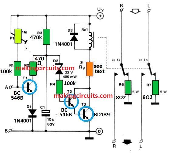
Their pros and cons will be discussed later in the piece of writing. No matter which circuit is used, A is shorted to B immediately the power is being turned on. T1, i.e. the cut off transistor is instantly being cut off by this – this causes capacitor C1 to charge.
The voltage across C1 causes zener D2 to break down after a few seconds. After that the transistor T2 and T3 conduct, and therefore the loudspeaker gets connected in circuit. Then the relay comes back to its quiescent stage, disconnecting the loudspeaker.
The input circuit, 1a, depends on a light dependent resistor which is placed close to the mains on indicator lamp. As soon as the lamp lights, the resistance of the LDR decreases sharply to virtually short the terminal A to terminal B.

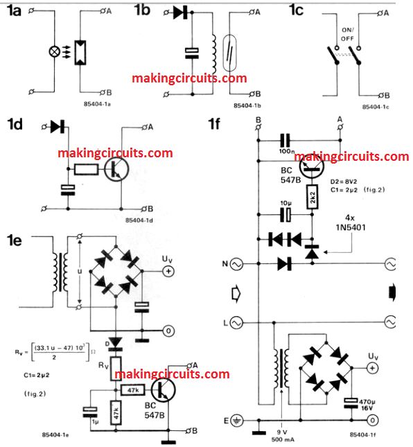
The input in 1b depends on a reed relay is being connected to the secondary winding which is in the mains transformer. The relay contacts readily gets closed, when the mains is switched on.
Another option for protecting loudspeakers from switch ON surge is shown in figure 1c – here the mains on and off switch consists of a third contact that connects A to B as soon as the mains is turned on.
The fourth protection option is drawn in figure 1d – here a transistor is connected to secondary of the mains transformer; this connection goes via a diode as well as a resistor. As soon as the mains is turned on, the transistor conducts.
The inputs in 1e, as well as 1f gives power for the protection circuit. 1e is used as a bridge rectifier. It is connected across the secondary winding of the mains transformer. As soon as the mains is turned on, the BC 547 conducts and shorts through A to terminal B.
In the end, the speaker protection circuit shown in figure 1f gets connected directly to the mains. Just like before, when the mains is switched on the BC547 conducts and terminal A is shorted to terminal B.
The use of input circuit depends entirely on circumstances and/or an individual’s preferences.
If one of the circuits shown in figure 1a to 1d is used, a separate supply of power is required for the protection circuit. The output voltage Uv, must be of 40 to 60 voltage. For lower value, however, the rating of D2 must be decreased accordingly.
Rv, the resistance depends on the relay used. The value is derived from the formula
Rv = [9Uv-Ur – 2.5)/ Ir] Ω,
Here Ur and Ir stands for operating voltage, expressed in volts and the current of the relay, expressed in amperes.
The relay contacts must have the ability to carry a large current: In many amplifiers, 10 A is not un- usual. The value of R, is [UrIr] W. If the 'plop is still heard, the value of R3 is needed to be increased.
How to Protect from Amplifier Short Circuit
The circuit is extremely adaptable and may be modified for a variety of uses. The plans cover applications for home audio, automobile, and commercial PA/guitar amplifiers. Catastrophic amplifier breakdown is the most prevalent cause of speaker damage. This is in contrast to the popular belief that a normally operating amp has overdriven the speaker.
Typically, the driving amplifier's power level is selected to match the speaker power rating. When high-current semiconductors, like bipolar power transistors and MOSFETs, burn up, they generally short the output. These devices are frequently connected directly to the DC power-supply rails of an amplifier or via a minimal amount of resistance which ca n’t properly restrict the current during the shorting period. The DC level of an amplifier's power supply is intended to handle the peak power levels which happen when the amp is driving the speaker at maximum output.
Power supply lines of a minimum 40 volts are required for a 100-watt amplifier. That amount would never be applied to the speaker coil for over a few seconds under typical working conditions. When an amp's external device short circuits, the DC is continually pushed to the speaker. This results in a power dissipation of:
This results in a power dissipation of: PD = (40V/speaker resistance) for a 100-watt amplifier 40V.
40V. The resistance of speakers is generally between one two ohms lower than the AC impedance. The power wasted by a blown amplifier attached to a 100-watt speaker with a 7-ohm DC resistance is:
PD = (40V/7Ω)40V = 228 watts


The speaker can only dissipate that power for a few seconds until eventually the coil is destroyed due to overheating. When the protector circuit detects a direct current voltage on the speaker line, it triggers a relay having contacts connected in series with the speaker; following two seconds, the relay switches OFF the speaker so that the DC is gone.
A fuse is insufficient for this application since the value required to protect the speaker from DC will burn out during regular operation at peak output levels. A fuse setting selected to enable peak power working levels, on the other hand, would not protect the speaker from a DC voltage.
The protector circuit allows for power level peaks while also protecting the speaker from direct current (DC). It can be used with a fuse value determined from peak power levels. The fuse should be positioned as close to the amplifier as feasible, if not in the same enclosure, and is thus not represented in the schematic of the protector circuit.
The voltage divider resistors R3-R6 are used to bias the positive and negative inputs of the window comparator produced by IC1-a and ICI -b, as shown in the diagram above. The inputs are biased at 3 volts plus and negative. The voltage divider also serves as a 9-volt reference for the comparator IC1 -c's negative input. The input voltage divider is formed by resistors R1 and R2, which are supplied from the speaker terminals of an audio amplifier. The input divider is linked to analogue ground, and the divider's output is attached to the negative and positive inputs of the window comparator (IC1-a and ICI -b). The open-collector outputs of IC1-a and IC1-b are connected with one another and driven high via R7. This accomplishes the window comparator by forming a wired OR function. When the voltage divider output surpasses the reference values defined by R4 and R5, the output of the window comparator swings low, removing the bias from Q1.
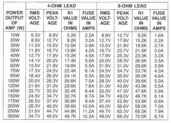
The value of R1 determines the input voltage at which this occurs. R1 is calculated using the formulae provided later in this article. While the output of the window comparator is low, transistor Q1 is switched off, enabling the timing capacitor Cl to continue charging through R8. The output of the window comparator will restore to a high level as soon as the input comes back to the plus and minus 3 volt range under typical input conditions (an AC audio signal). Q1 is pushed into conduction as a result, and C1 is discharged instantly. If a big enough DC signal is present on the input to activate the window comparator, QI will remain off and C1 will charge until it approaches 9 volts with reference to the power-supply ground When C1 hits 9 volts, comparator IC1-c is triggered, forcing its output to become high and biasing Q2 into conduction through R9. AS soon as Q2 is switched on, it grounds one terminal of relay RY1, energizing it and removing the audio from the speaker that passes through its contacts. The relay contacts will stay open until the DC input to the protector circuit is disconnected. Q2 is protected from reverse -bias spikes generated by the relay coil by diode D1.