


A voltage divider is basically an electronic circuit network using resistors. It is used for generating a proportionate amount of dropped voltage as the output depending on the values of the resistors.
In this network, resistors are connected in series across the supply voltage, and the output is extracted across one of the resistors for getting the desired equivalent dropped voltage.
Circuit of Voltage Divider
As explained above a voltage divider circuit can be built using a couple of resistors in different forms as given below
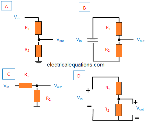
In the above shown diagrams, (A) signifies shorthand, (B) demonstrates longhand and (C) and (D) represents the resistor connections with elaborate details.
However, all the four conditions actually display the same configuration. The resistor R1 is always associated with the source supply positive. Resistor R2 is associated with the ground or the negative line of the source supply. Vout becomes the output which is gives the proportionately droppped voltage depending on the selected values of R1 and R2. Thus the T1 and R2 acts like a voltage divider giving rise to the intended Vout drop.
Voltage Divider Equation without Load
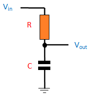
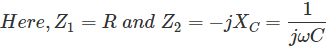
We can see a standard voltage divider circuit in the figure below. A couple of passive components having electrical impedances (Z1 and Z2) are attached in series. These components could be in the form of resistors or inductors or capacitors. The output of the circuit derived from across the impedance Z2.

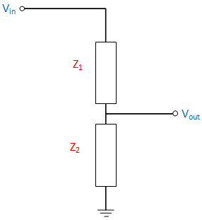
With an open output condition; no current will flow across the output side, then :
Vout = (Z2 / Z1 + Z2) x Vin --------------(1)
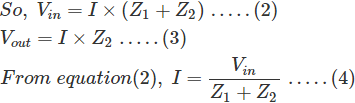
The above expression can be also solved using Ohm's Law:
V = I x R

Substitute equation (4) in equation (3), we are able to achieve the following:

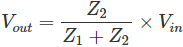
And this match proves the relationship.
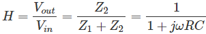
The transfer function of the above equation may be seen as:

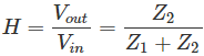
This equation is also called as Divider’s

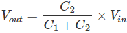
The capacitive divider circuits won't allow the passage of DC input through them, since these are designed to work only with AC.
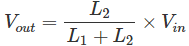
When the divider involves non-interacting inductors, the equation can be written as:


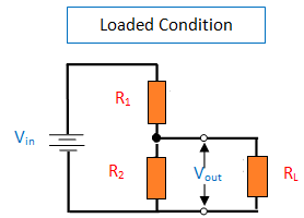
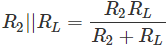
Voltage Divider Circuit with Load
Now let's understand a voltage divider network having a load connected with its output as shown below:

With the shown configuration, the equation number (1) discussed earlier can be applied as below:

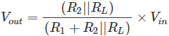
Since the output load becomes parallel to R2, the effective output potential drop can be evaluated with the formula:

Where Voltage Divider is Used
Applications of potential divider circuits include Logic level shifting, Sensing devices, high voltage scale down, Signal Level Attenuation.
You will also find voltage dividers in applications like multimeter and Wheatstone bridge.
The concept is further applied for developing reference voltages or for decreasing the magnitude of the voltage for the ease of measurement. In addition to this; at low frequency, it can be function as signal attenuators.
In DC circuits where low frequencies is involved, the resistor potential divider become very suitable. And when it comes to power transmission for high voltage capacitive voltage divider becomes the ideal choice.