The article describes a basic infrared (IR) centered motion detector circuit which includes the IC LM567 for being sure dependable and quick and easy procedures. The circuit as well functions as a proximity or difficulty detector circuit.
I discovered this design on the web while looking for a precise and trustworthy yet inexpensive proximity sensor circuit.
The circuit might be known with the aid of the following explanation:
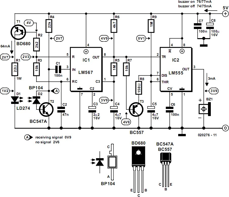
Talking about the below demonstrated infrared (IR) motion detector circuit, we refer to the design comprise of two main phases, one regarding the IC LM567 while the other with the IC555.
Essentially the IC LM567 turns into the heart of the circuit which exclusively works the functions of the generating/transmitting the IR frequency as well as detecting the same.
Furthermore the IC has an internal stage closed loop circuitry thereby making it seriously dependable with frequency detecting circuit applications.
This means as soon as it reads and latches to a given frequency, its detection function becomes closed to that frequency thereby some other stray disruption regardless of how powerful it might be does not affect or rattle its working.
An internal oscillator frequency identified by R3, C2 gives the IR diode D274 via a current managed step composed T1, R2. This frequency chooses the center frequency of the chip.
With the above problems the IC gets set and based at the above frequency producing a continuing high at its output pin#8.
Input pin#3 of the IC waits to be given a frequency which can be precisely equivalent to the above "centered" frequency of the IC.
The IR receiver or the sensor linked across pin#3 of the IC is placed specifically for this function.
As soon the IR beam from the LD274 discovers a difficulty, its beam receives reflected and drops on the properly located detector diode BP104.
The IR frequency from the LD274 currently transmits to the input pin#3 of the IC, given that this frequency is going to be precisely same to the set center frequency of the IC, the IC knows this and immediately switches its output from high to LOW.
The above low trigger at pin#2 of the IC 555 which can be set up as a monostable consequently switches its output high, leading to the associated alarm to blow.
The above problem continues for as long as the interruption from of the IR sensor/ detector remains and permits the beams to get shown. With the inclusion of R9 and C5, the output of IC555 displays a particular delay off condition for the attached buzzer even though the motion or the difficulty moves away.
For changing the delay-off impact, R9 and C5 could be modified according to choice.
The circuit could also be used as a proximity detector and obstacle detector circuit.