

Within this submit we understand an easy circuit which generates a LED scanner type illusion by means of the different sequencing illumination settings over the connected LED arrays.
In the exact knight rider LED scanner unit as presented in the video, you will discover at least 29 variety of features to be proper, employing those is practically not possible utilizing discrete elements and without using MCUs, in spite of this here we'll notice just how some of these might be likely made using just a couple of parts.
The main two features of the offered Mustang LED scanner circuit might be evaluated as presented in the following explanation:
1) LEDs illuminate in a bar mode fashion from the two ends of the strip and meet up at the center, lighting the entire module brightly.
Within the next series the LEDs commence closing off in an exact range as above from the outer significant ends until all the LEDs are turned OFF.
The rate or the speed of the above methods are adjustable by way of a pot according to individual choices.
2) The second scanning series resembles the above, apart from the shutting off process which can be completed for everyone the LEDs at the same time rather than separately.
The above two features may be very easily used making use of a number of 74LS164 ICs and a 555 IC oscillator as demonstrated below circuit diagram:


In the presented mustang scanner LED light circuit, several 8-bit parallel-out shift register ICs 74LS164 are being used, related to the IC555 set up as the clock oscillator.
The circuit could be recognized by thinking about the following two modes in the design:
As might be observed in the above circuit diagram, a 3 pole, 9 throw switch is utilized as the changeover switch for imitating the 2 services described in the earlier section above.
In mode1 S1 is attached as demonstrated in the circuit diagram, within this position the LEDs light up in an sequencing LED bar like fashion with every growing edge of the clocks from the IC555 until all the LED light up and the final "high" reaches pin16, when T1 briefly resets both the ICs creating in immediate shutting off of all the LEDs simultaneously.
In the specific prototype the LEDs from Q9----Q16 needs to be organized such that Q16 faces Q8, while Q9 faces the outer end of the pertinent strip.
The moment the above occurs, a new cycle is linked to afresh and the cycle repeats for provided the S1 position is just not transformed.
In mode 2 let's think about the switch S1 associated with the positive supply, hence S1a gets linked with the +5V line, S1b gets connected with the collector of T1 while S1c with R5.
Additionally the reset pin9 of IC1 and IC2 get associated with the collector of T1 whose base may be seen designed with the last output Q16 of IC2.
On power turn on, the LEDs start enlightening in a BAR like mode unchanged from Q1 to Q8 and from Q9 towards Q16 as a reaction to each clock pulses provided by the astable IC 555 at pin8 of the two 74LS164 ICs.
Right now the moment the high across the shifting outputs reach pin 16, T1 immediately inverts and provides a low to the serial pins1,2 of the ICs to ensure that right now the LEDs start shutting off one at a time across the arrays in a similar range as it lighted in accordance with every clock from IC555.
The technique maintains duplicating as long the switch S1 position is not modified from its current position.
The above two features are fairly conveniently executed and we certainly have our LEDs scan the complete array quite in the manner the actual Mustang scanner should preferably do, nevertheless with the above two services the capabilities appear a lot restricted and we may wish to insert just a few more of the benefits as could be observed in the original video.
I'll maintain the post updated with the new added abilities, but meanwhile let's find out how the LEDs might set up to the above scanner design according to the request made by Mr. Dannel.
For easy calculation and configuration we include 32 + 32 LEDs on each left and right strips.
The arrangement and the connection information might be confirmed by means of the following diagram:
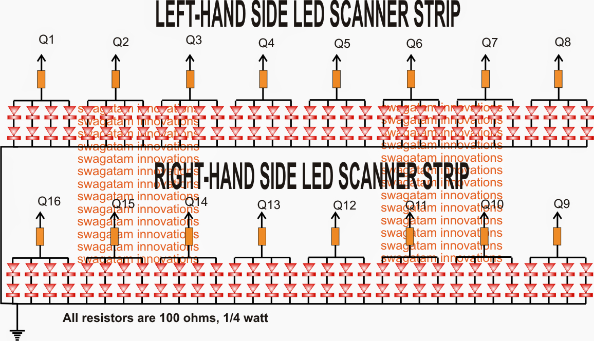
Mustang Knight Rider circuit LED wiring particulars
An additional fascinating scanner feature that may be very easily put into the above circuit with a function generating quick to and fro sequencing over the two strips in groups of four.
This may be conveniently made by toggling an arrangement in which T1 would certainly halt once all the LEDs turn on in bar like style.
Currently in this particular position a 4017 with its own oscillator would likely get into the scene with its outputs switching OFF the lit LEDs rapidly in a reverse forward manner. The switching might be carried out utilizing BJTs which might ground the appropriate anodes of the LEDs in the act.
Consequently we now have three attractive scanning sequences toggled in our very own homemade mustang LED scanner circuit, any further feasible remedies are accepted from the viewers.
