

A well balanced power supply is completely necessary for the precise functioning of computers and TTL circuits.
A voltage fluctuation of 10% is undoubtedly not bearable, it is therefore advisable to maintain a day-to-day check on the supply voltage level.


Due to their insufficient resolution and precision it is inadvisable to work with analogue panel meters to monitor the power supply voltage.
In addition to this, a fluttering pointer is barely the top choice for a warning device.
The LED voltage monitor circuit handles each one of these issues.
The voltage monitor is set up to ensure that simply the range among 4.5 V and 5.5 V is included.
The device used, the LM 3914, is extremely just like the LM 3915.
There is a minor variation amongst the two on the other hand: The LM 3915 features a logarithmic scale while the LM 3914 carries a linear scale.
The latter device includes a row of 10 identical 1 k 0 resistors.
The two reference levels, RLO and RHI, of the potential divider network P1, P2 and R4…R6, are set to 4.51/3 = 1.5 V and 5.41/3 = l.SV respectively.
The ' 3' is generated within the calculation as the input voltage is additionally split by three by resistors R1…R3.
The table indicates that LEDs will certainly light for the corresponding input voltage once the circuit has been set up correctly.

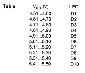
For a clear warning indication it is advisable to make use of red LEDs for Dl and D10 and green ones for the others.
This can possibly be helpful to make use of a different colour (orange) for D5 and D6 as an indication of the nominal voltage level.
The power supply for the circuit can be obtained from the voltage to be supervised as the current necessity is just 20 mA.
Diode D11 is included to safeguard the circuit towards reverse input polarity.
To adjust the circuit it should be attached to an adjustable regulated power supply.
The input voltage can now be altered until a reading of 5, 41 V is acquired on a digital voltmeter.
Potentiometer P1 can now be altered in order that D9 and D10 light up at the same time.
The input voltage is then set to a level of 4.61 V and P2 is modified to ensure that D1 and D2 light concurrently.
Since the internal resistors possess a minor impact on the circuit it is important to replicate the calibration method to discover the most effective accuracy.
To guarantee satisfactory performance of the LED voltage monitor, all resistors will need to have a tolerance of 5%