


The definition, operation, application, and characteristics of a light-to-frequency converter circuit will all be covered in this article.
Regardless of your background—professional, enthusiast, engineer, or student—modular components usually cut down on the amount of trouble we have while developing circuits by half.
They successfully save costs and do away with the requirement to develop unique circuits. The TSL235R light-to-frequency converter is one example of a modular component.
Understanding the Light to Frequency Converter TSL235R
So what exactly is this thing called a light to frequency converter known as the TSL235R? Well let me break it down for you in a more casual way. This little modular component is essentially an integrated circuit or IC for short that has the cool ability to transform the intensity of light into a frequency signal while maintaining a duty cycle of fifty percent.
Now here is where it gets interesting: the relationship between light intensity and frequency is directly proportional. This means that when the amount of ambient light or any external light increases, the output frequency also goes up. On the flip side if the light intensity decreases you can expect the output frequency to drop as well.
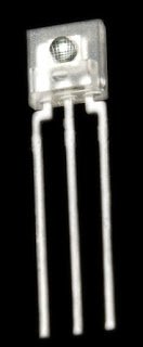
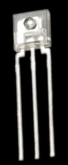
As for the physical appearance of the TSL235R, it is a three-legged device that resembles a transistor and features a translucent casing. It actually comes in two different styles; one version is designed for surface mounting while the other is made for the more traditional PCB mounting.
One of the standout benefits of using this particular IC is that it does not require any additional external components to generate a frequency signal. This makes it super convenient because you can connect it directly to any microcontroller or microprocessor without any hassle.
Additionally this module has a small bulged lens located at the front which helps to focus incoming light while the back side of the device is flat. It is worth noting that this component is highly sensitive and can detect even the tiniest changes in light levels. So if you are looking for a reliable way to measure light intensity in terms of frequency the TSL235R might just be what you need!

Specification overview:
So lets talk about the TSL235R parameters! This nifty little device can run on a power supply that ranges anywhere from 2.7 volts up to 5.5 volts with 5 volts being the sweet spot most folks aim for.
When it comes to light sensitivity, the TSL235R is pretty impressive, responding to a broad spectrum of light from 320 nanometers all the way to 1050 nanometers. This means it can detect everything from ultraviolet light to visible light which is super handy! Plus it operates well in a variety of temperatures, specifically from a chilly -25 degrees Celsius to a warm +70 degrees Celsius.
Now if we dive into some technical details, this device has a temperature coefficient of about 150 parts per million for every degree Celsius change. It can also handle frequencies like a champ—delivering a maximum frequency of 100 kilohertz and dipping down to a minimum frequency that’s in the range of a few hundred hertz.
One thing to note is that the output duty cycle is precisely calibrated to be 50% ensuring reliable performance. In terms of size, this little gadget measures about 19.4 millimeters in length (including its terminals) and has a width of around 4.6 millimeters.
To make sure everything runs smoothly you’ll need to connect a capacitor that falls within the range of 0.01 microfarads to 0.1 microfarads from its power supply terminal. And remember it’s best if that capacitor is placed as close as possible to the TSL235R itself for optimal functionality.
How it works?

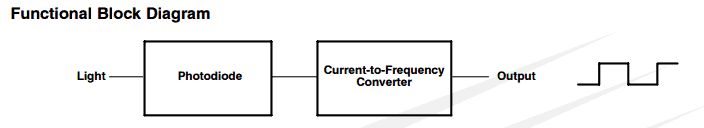
What we have here is a nifty little setup that consists of two main parts: one is a silicon photodiode, and the other is something called a current to frequency converter or CFC for short. Now the CFC is basically a piece of circuitry that takes the current flowing through it and converts that into a frequency. Pretty cool, right?
Now heres the interesting bit, the amount of current that flows through the photodiode is actually linked to how much light is hitting it. So when there’s more light, more current flows through the photodiode. The CFC keeps an eye on this current flow and adjusts the frequency accordingly.
If the current goes up because there’s more light, the frequency goes up too and if the current goes down so does the frequency. This gives us a neat way to indirectly convert light into frequency!
How Can You Use This.
Now you might be wondering where you can actually put this TSL235R to good use. Well it’s perfect for any project that involves light! Here are some fun ideas:
Measuring Ambient Light: You can use it as a lux meter to measure how much light is around you.
Feedback Circuits in Inverters: If you’re working with an inverter and want to stabilize its output regardless of what load is connected, you can couple a LED with the TSL235R for some effective feedback.
Motion Detection: Its also great for motion detectors since it can pick up any changes in light intensity.
Security Systems: You can incorporate it into security systems to enhance their functionality.
Automatic Street Lights: Imagine an automatic street light system where a microcontroller detects a drop in frequency and turns on the lights—super handy.....

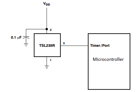
This is an example of how to connect it to a microcontroller.
Once you start using it and grasp it properly, the possibilities are limitless.
Circuits for Applications
Leveraging the above described IC TLS235R, one can will attempt to comprehend a few intriguing light frequency converter application circuits in the paragraphs that follow.
1) Adaptable Circuit for Light to Frequency Generator

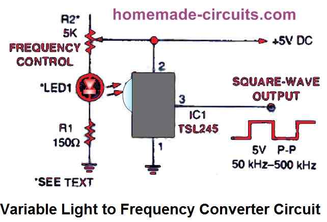
Our First Design Overview
So let’s get into our very first design which you can see up above. In this setup we’re using a potentiometer labeled R2 to control the frequency. Whats really cool about this is that it allows us to generate square waves with a frequency that we can easily adjust, ranging anywhere from 50 kHz all the way up to about 500 kHz.
Now let’s talk about how we’re getting the signal into the circuit. We have an infrared (IR) LED that operates at a peak power of 880 nm, and it’s positioned to shine directly at the input window of the TSL245. This input window is that little, rounded bump you see on the front of the integrated circuit (IC).
Creating a Light-Proof Enclosure
It’s super important to create a light-proof enclosure for the IR LED and photodiode pair. Why? Because if any outside light sneaks in and hits the photodiode, it can really mess things up and render it ineffective.
The minimum amount of light that manages to reach the photodiode sets the slowest frequency at which our circuit can operate. In fact if we’re in complete darkness, the output frequency might drop below 1 Hz! When you crank R2 up to its maximum resistance and the LED is shining its dimmest, that’s when you’ll find the circuit running at its lowest frequency.
Adjusting for Audible Frequencies
If you want to tweak things a bit, you can swap out R2 for either a 10k resistor or a 20k potentiometer. This change will allow our square-wave generating circuit to operate within the audible frequency range, which is pretty neat!
If you find that your circuit isnt working well in that lower frequency range, try temporarily disconnecting power from the IR LED and check what output frequency you’re getting.
Troubleshooting Frequency Issues
Now if you notice that the frequency level goes above 50 Hz, there’s a good chance that some ambient light from outside is hitting the photodiode. To troubleshoot this focus some bright ambient light on your setup and see if that causes an increase in frequency.
If nothing seems to change at all, then congratulations.... It looks like your enclosure is doing its job perfectly by keeping everything sealed off from outside light. However if you do see an increase in frequency, it’s time to hunt down any light leaks and cover them up to keep your circuit functioning properly.
Light Dependent Tone Generator Circuit

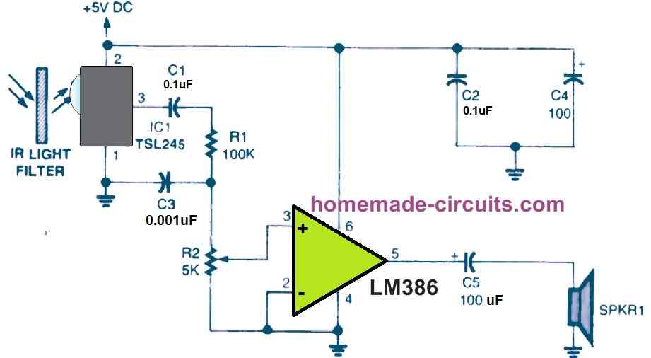
So in the circuit we’re talking about, the TSL245 is playing a key role as part of a light-seeking device. What it does is pretty cool, it generates an audio tone that changes based on how much infrared (IR) light hits the integrated circuit.
Now while this IC does come with its own built-in IR filter we still need to add some extra filtering to make sure the circuit works well in the music frequency range especially when we're in a typical environment with regular ambient light.
One interesting way to create a suitable IR filter is by using the exposed and developed ends of a 35mm film or something similar. If those film ends are really dark and you layer them in front of the IC as needed, the circuit can produce an output signal ranging from 2 to 8 kHz even when theres normal lighting around.
The number of layers of film you use will actually determine the highest frequency that the circuit can handle. On the flip side, the least amount of light that gets through to the photodiode in the IC will set the lowest output frequency.
Let’s get into how this circuit works and what it can do! The TSL245 responds to ambient light hitting it (that’s IC1) and this response is connected through components C1, R1, and R2 to an LM386 audio power amplifier IC. To keep things from getting too high-pitched, C3 helps filter out those higher frequencies and sends them to ground.
The amplifier drives a small 4-ohm speaker. If you want to lower the output frequency (or pitch), just wave your hand over the TSL245. You’ll notice that when you completely block the light with your hand or any other opaque object, the sound drops down to its lowest frequency.
Now if you’re interested in a similar setup you can also create a light-to-frequency converter using an IC 555. Just wire it up in astable mode and swap out one of its resistors for an LDR (light-dependent resistor), like shown below::

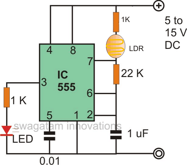
Depending on the requirements of the usage, different values of the capacitor C1 could be used to generate different sets of frequency ranges.
Whatever desirable external load or circuit could be connected to pin 3 of the IC 555; however, if a TTL equivalent output is needed, be certain to provide the IC 555 with an accurately measured 5V.