

A liquid level sensor is a device which is used for detecting the level of a given liquid inside a container through an electrical conduction across a given set of probes.
By: Swagatam (image courtesy: elektor electronics)
Introduction
In the proposed circuit, we employ an oscillator, whose frequency is applied across a given probe ends, and this probe is positioned at the specified level inside a tank or container wherein the liquid level is required to be sensed.
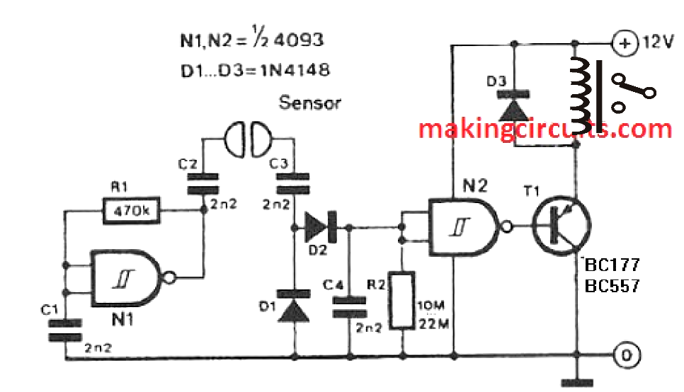

Using CMOS Gates for the Sensing
As shown the above circuit diagram, just a couple of CMOS gates are used for the application which can be achieved using a single IC 4093.
Since the IC 4093 consists of 4 such gates in it, gives you the freedom of building two such units and apply it for detecting and controlling two liquid level simultaneously.
For your information, the IC 4093 consists of 4 or quad NAND gates with Schmitt trigger property, a feature which allows the gates to work with a small amount of hysteresis which in turn allows better accuracy and control of the system.
In our liquid level sensor application, two such NAND gates are used, however the NAND gates here are used like inverters by shorting their input pins. To be precise here the NAND gates work like NOT gates with Schmitt trigger facility.
The first gate N1 is configured as an oscillator for applying the frequency across the sensing probes.
Why an oscillator
Well, an oscillating electrical pulsed detection of the fluid across the probes helps the probes to remain corrosion free and long lasting.
Especially when this fluid sensor circuit is used as a water level sensor circuit, the probes may be required to remain immersed inside water for many occasions causing persistent oxidation of the probe metal.
However with the use of an oscillating electrical signal across the probes, the issue of corrosion is greatly reduced.
The second gate N2, is arranged in the form of a buffer sage for accepting a conducting path across the probes whenever the fluid or water reaches the probe level.
As soon as this is detected, minute pulsating current hit the input of N2, causing a high logic here.
This high logic causes an opposite or inverted low logic at the output of N2, enabling the PNP BJT to trigger instantly. The triggering of the BJT in turn actuates the relay which ensures an immediate cut off for the rising liquid by switching off the relevant pump through its contact wiring.
The relay is required to be wired appropriately with the pump motor of the fluid or the water pump, depending on which fluid is used inside the container for the sensing and cut off.
If you have any further doubts regarding this simple fluid level detector circuit which can be also used as a simple corrosion free water level controller circuit, please drop a line in the below given comment section for getting quick replies.