

The circuit described here works as a logic tester for TTL circuits, CMOS circuits as well as other logic families with similar behavior. The circuit is capable of indicating an undefined logic level and open circuit connections besides the usual logic 0 and logic 1.
A voltage below 0.8 V is low or logic 0 and above 2 V is high or logic 1 for TTL circuits, with anything in the middle being an undefined logic level. The supply range for operation of a CMOS logic is much greater, usually, around 3-18 V. The logic levels in this are indicated as a percentage of the supply voltage instead of absolute values.
Above 60 % of the supply voltage is the high logic level and below 40 % is the low logic level. There is no clear distinction between the levels within these limits.
A logic probe is supposed to be able to differentiate between high, low and undefined levels of logic. There is also a chance of coming across an open circuit due to a circuit fault or the test probe being unable to make good contact when using the logic tester.
Another possibility is an NC or No Connection, which is a manufacturer’s term for deliberately not keeping the pins connected. A proper logic tester should be able to indicate an open circuit differently from other logic levels.

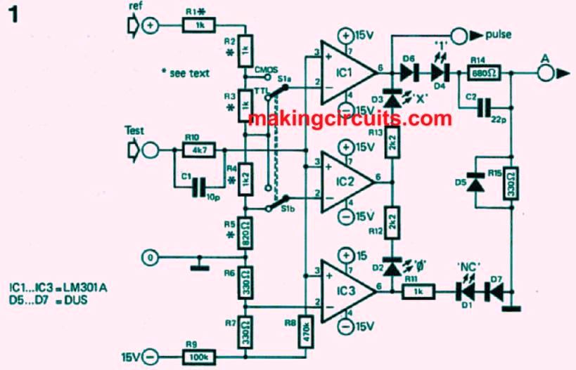
Figure 1 illustrates the main logic tester circuit. There are four possible input conditions, so three voltage comparators are used to identify them. The supply lines of the logic circuit being tested are attached with the reference or “ref +” and the “0” terminals of the logic tester. When S1 is at “TTL” position, a 5 V supply will result in 2 V at the inverting input of IC1 and 0.8 V at that of IC2. When S1 is set to “CMOS” setting, 60% and 40% of the supply voltage of the test circuit will be noticed for the respective reference voltages.
A voltage of -50 mV is fed to the inverting input of IC3 from the ±15 V supply of the tester through R9, R7 and R6. If the test circuit is open, the inverting inputs of the three comparators will become -100 mV through R8.
Since outputs from all three of them would be negative in that case, it would light up LED D1. in the case of the test input being connected to a voltage 0 V and the 0 logic level, the output of IC3 will be positive.
Thus, the current will flow from the output of IC3 to that of IC2 through D2 and light it up to indicate “logic 0”.
When the voltage lies between the logic 0 and logic 1 levels, the output of IC2 also becomes positive, causing D2 to turn off and D3 to light up as current flows from the output of IC2 to that of IC1 through it. This stands for the undefined logic state “X”. When the voltage exceeds the logic 1 level, the IC1 output becomes positive and D4 lights up as D3 goes out to indicate logic 1.
Pulse Indication
Pulses and pulse trains are quite common in logic circuits, while the above explanation was for static levels only. When a pulse train with close to 50% duty cycle is
encountered, the D2 and D4 LEDs will glow together dimly. However, with pulse trains of very high or very low duty cycle, one LED will seem to be lit uninterruptedly.

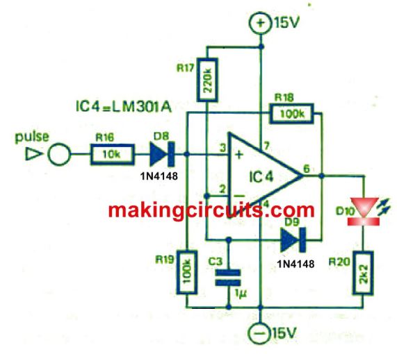
Whereas short single pulses will remain undetected altogether. This is solved using a “pulse stretcher” as seen in Figure 2.
This is a one-shot multivibrator that has an output pulse period of around 200 ms. When a pulse is encountered at the point labelled “pulse”, connected to the input of the pulse stretcher, as seen in Figure 1, it will trigger the one-shot and light the LED for 200 ms, which is long enough for detection. For pulse rates over 5 Hz, D10 will seem to be lit constantly.
For simple frequency counters and the like, a TTL-compatible pulse output is used (A). In case it is unnecessary, C2 and D5 are not needed either and a single 1 k resistor can be used instead of R14 and R15