An alarm that gives indication of a low battery voltage, discharged at around 10.5 Volts in vehicles such as Boats and Cars can be made using a simple circuit. It is better than Indicators which shows a glowing light that can be missed by the drivers.
The Circuit
The circuit of the low voltage alarm consists of a 555 astable that generates the loudspeaker alarm signal. To let the astable work, pin 4 of 555 is provided with some voltage.

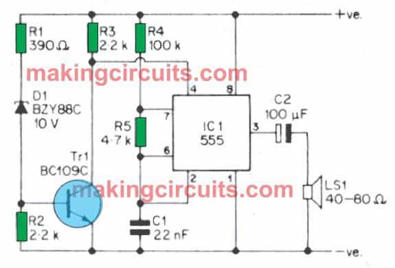
D1 gets biased and creates conduction if the voltage supplied to it is more than 10.5 Volts or its avalanche voltage. This helps R2 to have sufficient Voltage across it when Tr1receives around tens of thousands of minivolts which stops the audible signal.
When the voltage of 10.5 keeps D1 in a mode of conduction, the charging around it helps leave voltage across R2. When Tr1 cuts off, R3 turns pin 4 of IC1 completely charged positive. This enables the astable to start working again. Therefore the alarm signal starts ringing again once the voltage goes down 10.5 volts at D1.
The circuit has a consumption of 10mA which is insignificant for a large 12 Volt battery used in the vehicles.
Construction
The construction of the alarm can be made with an on/off switch to stop or start the bell ringing. In this circuit, the threshold voltage can be altered as and when desired. To do so the operating Voltage of D1 has to be changed.
There is Voltage difference between D1 and a zender diode is 0.5 volts. However, the latter can be used instead of D1 too. Nevertheless, there is a limit of threshold voltage that is maximum for the circuit.
The upper limit of voltage is 16 Volt of the 555 device. So, it must not be used where there is a danger of higher voltages.
There is a chance of an error of 0. 5 volts in the circuit but that’s quite permissible.
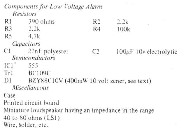
Parts List