

The post discusses a circuit which can be used for testing mains wiring phase, neutral, earthing line faults simply through 3 neon lamp illumination with a specified pattern, let's learn the details.
In this article we include yet one more easy circuit, which involves a couple of neon lamps (with integrated series resistors) a push-button and an optionally available 100 k resistor.
Could this particular circuit truly be regarded as as a piece of ‘test equipment? Needless to say it can. In fact basic concepts are those that are applied repeatedly right up until they turn out to be indispensable.
Think about just how simple a phase tester is! On the other hand, all those gadgets can only display whether or not the ‘live’ mains network is OK, which leaves the person speculating regarding the negative and earth lines. . .
But not any longer! The mains wiring tester proven in this article will certainly make it possible for all the 3 lines to be examined by basically demanding a button.
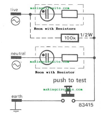

While the circuit is actually coupled to the mains each neons will probably illuminate dimly. When the push button is at this point pushed one lamp will shut out fully and another will light up adequately.
This in reality informs us about three issues: there exists a phase current, the ‘live’ path may be the one with the illuminated neon, and all 3 lines (live, neutral and earth) are functioning. In accurately wired household networks, the live and neutral contacts are usually recognized beforehand.
In this instance an additional 100 k resistor could be included as shown. The bottom neon must subsequently light in the beginning; running the push button must trigger the upper neon to illuminate. Any other outcome may signify a wiring fault!
If you have any doubts regarding this mains wiring fault tester, please consider commenting below.