

When powered this circuit, it generates the well-known lights that could be observed in most police cars. To accomplish the preferred effect 2 sets of lamps were employed (in our case: LEDs), which are turned on alternately.

The moment a group is switched on, the associated LED turns on and off 3 times. After that the other array is activated which is the identical. The procedure is continued endlessly.
This appearance is just like strobe lights that sometimes can be seen in the party halls and other similar places are.
While the police car circuit works
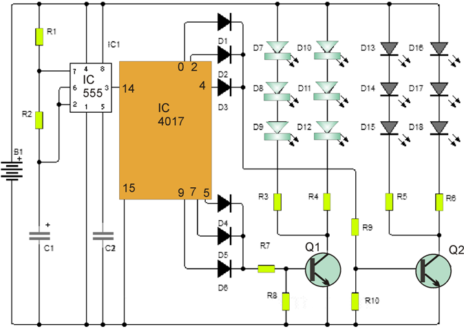
The circuit takes advantage of a 555 that drives and acts as a clock counter 4017B decade clock generator.
Altering the values of resistors and capacitor attached to the 555 timer it is possible to adjust the time clock rate. Even though the values shown are quite sufficient to cause the circuit to perform fairly well.
The 4017B provides sequentially activating logics in each of its outputs a signal equivalent to the supply level or of high level. When only the outputs become 0, is well ensured that 2, 4, 5, 7, 9 are engaged.
This is achieved to produce the flashing of the diode while each one group of LEDs is linked together.
Notice the outputs 1,3,6 and 8 are not attached and the time needed to generate the display LEDs off.
The first array of LEDs hooked up to the outputs 0, 2 and 4, and the second group is linked with the outputs 5, 7, 9.
Number of circuit parts
- IC1: 555 timer
- IC2: decade counter 4017B
- Q1 = Q2: 2N2222 bipolar transistor or the like
- D1 = D2 = D3 = D4 = D5 = D6 1N4001 diode
- D7 to D18: LEDs
- R1: 1K resistor
- R2: 22K resistor
- R3 to R10: 470 ohm resistors
- C1: Electrolytic capacitor 2.2uF
- C2: 0.01uF capacitor.
The circuit is driven by a 12VDC supply or a battery of the matching voltage as that of the automobiles (B +).