

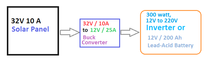
Let us imagine that we want to design a circuit for a 300 watt inverter operating at 12 volts using a solar panel that is rated at 32 volts and capable of delivering 15 amps.
To achieve this we will need our buck converter to provide an output current calculated by taking the total wattage which is three hundred watts divided by twelve volts resulting in an output requirement of twenty five amps from the buck converter.

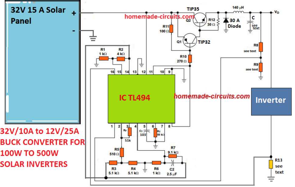
The following simple buck converter design found on ti.com appears to be highly efficient in supplying the necessary power for our 300 watt solar inverter project.

Let us take a moment to discuss how we go about fixing the essential parameters of the buck converter based on the calculations that follow.
Design Requirements
First things first we have the specifications for our design which include the following important values. The voltage from the solar panel is specified as thirty-two volts. The output voltage from the buck converter is set to twelve volts.
Additionally we need the output current from the buck converter to be twenty-five amps. The operating frequency for the buck converter is established at twenty kilohertz which refers to the switching frequency.
We also have a peak-to-peak ripple voltage noted as twenty millivolts and the change in inductor current is set at one point five amps.
Now if we look at the duty cycle which is represented by the letter d we can calculate it using the formula VO / VI which gives us 12 /32 volts = 0.375
The frequency f is set to twenty kilohertz which aligns with our design objective.
Next we need to determine ton which represents the time when switch S1 is closed. We can calculate this using the formula 1 / f * d = 7.8 microseconds.
Then we have to find toff which is the time when switch S1 is open. This can be calculated by taking one divided by f and subtracting ton resulting in forty-two point two microseconds.
1 / (f - ton) = 42.2 us
Now let us move on to calculating L which represents the inductance. This can be approximated using the formula (VI minus VO) multiplied by ton divided by ΔIL.
L = (VI - VO) / ΔIL
Plugging in our values we get [(32 volts - 12 volts) * 7.8 microseconds] / 1.5 amps giving us approximately 104 microhenries.
This calculation provides us with the specifications needed for the buck converter inductor.
The wire gauge known as SWG can be optimized through some trial and error and a sixteen SWG super enameled copper wire should suffice for handling a current of twenty-five amps.
Calculating the Output Filter Capacitor for the Buck Converter
Once we have determined the output buck inductor we can proceed to work out the value of the output filter capacitor so that it matches our output ripple specifications.
An electrolytic capacitor can be thought of as having a series relationship that includes an inductance a resistance and a capacitance. In order to achieve decent ripple filtering it is crucial that the ripple frequency remains significantly lower than those frequencies where series inductance becomes critical.
Thus we need to focus on two key elements which are capacitance and effective series resistance also known as ESR. The highest ESR can be calculated based on the relationship between our chosen peak-to-peak ripple voltage and peak-to-peak ripple current.
To find ESR we use the formula ΔVo(ripple) divided by ΔIL resulting in V divided by one point five giving us zero point zero six seven ohms.
Next we need to determine the minimum capacitance value C that is recommended to manage the output voltage ripple keeping it below our design requirement of one hundred millivolts.
This can be expressed through calculations where C equals ΔIL divided by eight times f times ΔVo which results in one point five divided by eight times twenty times one thousand times zero point one volts giving us ninety-four microfarads although having a higher value than this will only serve to enhance the output ripple response of our buck converter.
Setting up the Buck Output for the Solar Inverter
Now moving on to setting up our output at twelve volts and twenty-five amps we need to calculate some resistors namely R8 R9 and R13.
The resistors R8 and R9 play a crucial role in determining our output voltage which can be adjusted by using a ten kilohm resistor for R8 along with a ten kilohm potentiometer for R9. Following this we will adjust that ten kilohm potentiometer until we achieve precisely the right output voltage for our inverter.
R13 serves as our current sensing resistor within the buck converter ensuring that our inverter does not draw more than twenty-five amps from our solar panel and will shut down if such a scenario occurs.
Additionally resistors R1 and R2 are responsible for establishing a reference voltage of approximately one volt for the inverting input of an internal current-limiting operational amplifier known as TL404.
Resistor R13 which is connected in series with our load delivers one volt to the non-inverting terminal of this current-limiting error operational amplifier as soon as our inverter current reaches twenty-five amps.
Consequently this allows us to appropriately restrict PWM for BJTs thereby controlling any further intake of current. The value for R13 can be calculated using this formula:
R13 equals one volt divided by twenty-five amps resulting in zero point zero four ohms.
For wattage calculations we have one multiplied by twenty-five yielding twenty-five watts.
Once all these components for our buck converter are built and tested ensuring that they effectively convert excess panel voltage into excess output current it will then be time to connect a good quality three hundred watt inverter with our buck converter utilizing a block diagram that follows.