In this post we will learn how this solid-state solar charger works and how we can build it, step by step. This one is mainly for new hobbyists who are just starting so we have kept it simple and pictorial so that anybody can refer to it and make it without much difficulty.
Now this design is very simple and cheap which makes it perfect for village street lighting or remote areas, but that does not mean it cannot be used in cities. It is good for anywhere street lighting is needed.
Main Features of This System
Now here we will see the most important features that make this system work efficiently:
Voltage Controlled Charging – This makes sure the battery charges at a safe voltage.
Current Controlled LED Operation – The LED module gets only the required amount of current, so it does not get damaged.
Fully Solid-State Design – No relays only transistors and ICs which makes it long-lasting and reliable.
Low Critical Voltage Load Cut-Off – The system automatically shuts down the LEDs when the battery voltage gets too low.
Low Voltage and Critical Voltage Indicators – LED indicators tell us when the battery is getting low or is about to shut down.
No Overcharge Cutoff – We did not include this because the charging is already controlled at a safe level so the battery will never overcharge.
Easy to Find Parts – We use popular ICs like LM338 and transistors like BC547 so there is no trouble in finding these parts.
Automatic Day/Night Sensing – This system turns OFF at sunrise and turns ON at sunset so we dont have to worry about manually switching it.
How the Circuit Works
Now let us look at how this circuit actually works and what each stage does, right?
Step 1: Battery Voltage Monitoring Stages
The circuit has two battery monitoring stages, both working in exactly the same way, one using T1, T2, P1, and the other using T3, T4, P2.
The T1, T2 stage is designed to detect 13V. When the battery voltage drops to 13V, then LED connected to T2 turns ON.
The T3, T4 stage is designed to detect below 11V, and when the battery voltage falls below 11V then LED connected to T4 lights up.
P1 and P2 are used for adjusting these voltage levels so we can set them exactly where we want.
Tip: Adjust P1 carefully so that T2 LED turns ON exactly at 12V and P2 so that T4 LED glows when voltage falls below 11V.
Step 2: Solar Panel Voltage Regulation Stage
Now we have IC1 (LM338), which is a voltage regulator.
This IC takes the high voltage from the solar panel and regulates it to exactly 14V so that the battery gets the proper voltage.
The preset P3 is used for adjusting this voltage.
Tip: Before connecting the battery measure the output voltage of IC1 and make sure it is set to exactly 14V.
Step 3: LED Current Control Stage
Next we use another LM338 (IC2) but this time it is wired in current control mode.
IC2’s input is connected to the battery and output goes to the LED module.
This ensures that only the right amount of current flows to the LEDs so they operate safely and do not burn out.
Tip: If you want to increase or decrease LED brightness you will have to change the current limit in IC2 by selecting the correct resistor value.
Step 4: Critical Low Battery Cut-Off (T5 Transistor Stage)
Now here comes T5 which is a power transistor working like a switch
T5 is controlled by the critical low battery stage (T3/T4 stage).
So whenever the battery voltage goes below the danger level T4 grounds the base of T5 immediately turning it OFF.
When T5 turns OFF the LED module also shuts OFF preventing the battery from getting deeply discharged.
Tip: If the battery voltage becomes too low we might need to charge it externally using a 24V power supply connected to the solar panel lines.
Step 5: Automatic Day/Night Switching (T6 Transistor Stage)
Now to automatically turn the LED module ON at night and OFF at dawn, we use T6 transistor.
T6 is connected in such a way that it detects solar panel voltage and keeps the LEDs OFF when there is enough sunlight.
But as soon as it gets dark, then solar panel voltage drops and T6 allows the LED module to turn ON.
In the morning, then opposite happens, the solar panel starts generating voltage and T6 shuts OFF the LEDs.
R12 and R13 are very important here because they set the exact light threshold for switching.
Tip: Adjust R12 and R13 carefully so that the LED module turns ON only when it is really dark and turns OFF as soon as there is enough daylight.
Now What Should We Check Before Powering It ON?
Measure all voltages using a multimeter and ensure everything is set correctly.
Check the IC1 output voltage, it should be 14V before connecting the battery.
Adjust P1 and P2 properly so that the low battery indicators work at the right voltages.
Ensure T5 is switching correctly by testing with a partially discharged battery.
Place the solar panel in proper sunlight, and check whether it charges the battery properly.
Once all these tests are done then we can now let the system work on its own and it will automatically manage charging, LED operation and battery protection without any manual intervention!
Circuit Diagram

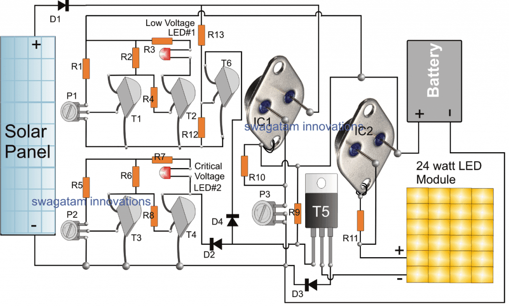
The circuit stage comprising T1, T2, and P1 are configured into a simple low battery sensor, indicator circuit
An exactly identical stage can also be seen just below, using T3, T4 and the associated parts, which form another low voltage detector stage.
The T1, T2 stage detects the battery voltage when it drops to 13V by illuminating the attached LED at the collector of T2, while the T3, T4 stage detects the battery voltage when it reaches below 11V, and indicates the situation by illuminating the LED associated with the collector of T4.
P1 is used for adjusting the T1/T2 stage such that the T2 LED just illuminates at 12V, similarly P2 is adjusted to make the T4 LED begin illuminating at voltages below 11V.
IC1 LM338 is configured as a simple regulated voltage power supply for regulating the solar panel voltage to a precise 14V, this is done by adjusting the preset P3 appropriately.
This output from IC1 is used for charging the street lamp battery during day time and peak sunshine.
IC2 is another LM338 IC, wired in a current controller mode, its input pin is connected with the battery positive while the output is connected with the LED module.
IC2 restricts the current level from the battery and supplies the right amount of current to the LED module so that it is able operate safely during night time back up mode.
T5 is a power transistor which acts like a switch and is triggered by the critical low battery stage, whenever the battery voltage tends to reach the critical level.
Whenever this happens the base of T5 is instantly grounded by T4, shutting it off instantly. With T5 shut off, the LED module is enable to illuminate and therefore it is also shut off.
This condition prevents and safeguards the battery from getting overly discharged and damaged. In such situations the battery might need an external charging from mains using a 24V, power supply applied across the solar panel supply lines, across the cathode of D1 and ground.
The current from this supply could be specified at around 20% of battery AH, and the battery may be charged until both the LEDs stop glowing.
The T6 transistor along with its base resistors is positioned to detect the supply from the solar panel and ensure that the LED module remains disabled as long as a reasonable amount of supply is available from the panel, or in other words T6 keeps the LED module shut off until its dark enough for the LED module and then is switched ON.
The opposite happen at dawn when the LED module is automatically switched OFF. R12, R13 should be carefully adjusted or selected to determine the desired thresholds for the LED module's ON/OFF cycles.
How We Build This Step by Step?
Ok now if we want to complete this simple street light system correctly then we must first build all the small circuit sections one by one and check them separately before we join them all together, right?
If we try to make everything at once then something may go wrong and we may not understand where the mistake is so it is always better to check each part first.
Step 1: Building the First Voltage Indicator Stage (T1, T2)
Now first of all we assemble the T1, T2 stage ok? This means we take T1, T2, R1, R2, R3, R4, P1 and the LED and connect them together exactly as per the schematic.
Now to check if it is working or not, we take a variable power supply and apply exactly 13V to this stage. Now slowly we adjust P1 until the LED just starts glowing, right? That means it has detected 13V correctly.
Now we increase the supply voltage a bit maybe to 13.5V and now the LED should turn OFF. Then if this happens then it means our low voltage indicator is working perfectly. Ok? Done!
Step 2: Building the Second Voltage Indicator Stage (T3, T4)
Now we repeat the exact same process for the T3, T4 stage. This time we take T3, T4, P2, and the related parts and assemble them.
Now again we take the variable power supply but this time we apply exactly 11V. Now we adjust P2 carefully until the LED just begins to glow.
Then if this happens then it means our second low voltage detection stage is also working and this 11V level will now act as the critical low battery shutdown point. Done!
Step 3: Setting Up the IC1 (LM338) Stage for Voltage Regulation
Now after these indicator stages are done, then we move to the IC1 stage. Here IC1 (LM338) is used as a voltage regulator so we need to set its output correctly before connecting anything else, right?
So now we take the IC1, connect it as per the circuit diagram and apply 20V or 24V across its input pin and ground.
Now we take a multimeter and measure the voltage between IC1’s body and ground. Then if it is not 14V then we slowly adjust P3 until we get exactly 14V. Ok? Once this is set, then we can say that IC1 is ready for charging the battery safely. Done!
Step 4: Setting Up the IC2 (LM338) Stage for LED Current Control
Now let us move to IC2 (another LM338) which controls the LED current. We just build this stage as shown in the diagram and here we do not need to adjust anything manually.
The only thing we need to set is R11 because R11 decides the current limit. We can calculate R11 using the LM338 current controller formula which is:
R11= Required Current / 1.25
So now we calculate R11 based on how much current our LED module needs, then we select the closest resistor value and connect it. Done!
Final Step: Connecting Everything Together
Now once all these individual sections are tested separately, we can connect them together and test how the whole system works! Then if we have done everything correctly then our fully solid-state solar LED street light circuit will start working automatically, turning ON and OFF by itself without any manual operation.
That is it, done!
Parts List
| Component | Specification |
|---|---|
| R1, R2, R3, R4, R5, R6, R7, R8, R9, R12 | 10k, 1/4 WATT |
| P1, P2, P3 | 10K PRESETS |
| R10 | 240 OHMS, 1/4 WATT |
| R13 | 22K |
| D1, D3 | 6A4 DIODE |
| D2, D4 | 1N4007 DIODE |
| T1, T2, T3, T4 | BC547 |
| T5 | TIP142 |
| R11 | SEE TEXT (Depends on current setting) |
| IC1, IC2 | LM338 IC (TO-3 package) |
| LED Module | 24 x 1W LEDs (Series & Parallel Connection) |
| Battery | 12V SMF, 40AH |
| Solar Panel | 20V/24V, 7 Amp |
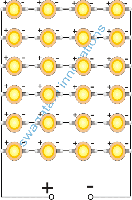
Making th 24 watt LED Module
As seen in the accompanying graphic, 24 nos of 1 watt LEDs might be joined to create the 24 watt LED module for the aforementioned basic solar street light system: