


So you might be wondering what a water level indicator is. Well it is actually an electronic circuit that helps you see the different levels of water inside a tank.
This works by using water sensors that are set up in a stepwise manner at various depths inside the tank. When the water level goes up or down and touches these sensors, it sends a signal to indicate the current water level.
In this post you are going to learn a simplest way to create simple water level indicator circuit using BJT BC547 only..
We will be using transistors some LEDs to make this happen.
What is Main Purpose of the Design
Now let’s talk about the main goal of this circuit. There are actually quite a few posts on this blog that explain how to build water level controller circuits. These circuits are designed specifically to switch on and off the motor pump when the tank fills up.
But here is the thing there are people out there who just want to know what the different levels of water in their tank are without needing an automatic shut-off feature. For them it is more important to have a simple indication of water levels rather than having the motor turn off automatically.
They prefer to turn off the motor by hand which they believe is a more reliable and safer approach for managing their water levels.
Water Level Indicator Using Transistors or BJTs
You probably already know that undistilled water can conduct electricity, but it does so with a bit of resistance. This resistance can range anywhere from about 100K to 500K ohms depending on how pure the water is.
This interesting property of water can actually be put to good use when it comes to switching transistors on and off.
What you can do is take advantage of this characteristic of water to control the base of a series of BJTs, which are bipolar junction transistors.
As the water level rises and falls it will interact with the sensors that are connected to the bases of these transistors allowing you to switch them on or off in a sequential manner.
To help us visualize this concept better let’s take a look at a simple circuit that illustrates how this works:

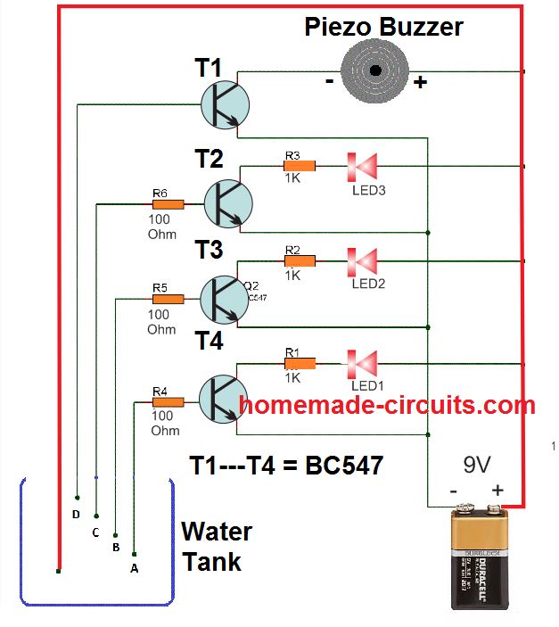
Circuit Description
The idea we are working with is as straightforward as it gets. Imagine we have the positive terminal of our power supply placed right at the bottom of the tank.
This way even when the water is at its lowest level it is still in contact with that positive terminal. Now what we do is arrange the bases of our transistors in a sequence all along the depth of the water tank.
This means that as the water fills up it will sequentially connect the positive supply to each of the relevant BJT bases through the rising water level.
So as the water level rises the transistors start getting biased one after another. This causes the collector LEDs to light up in the same order, which is pretty cool.
And then when the water finally reaches the top level of the tank that’s when our buzzer gets triggered by the very last BC547 transistor.
This whole setup really helps us as users to clearly see what the current water level is and also lets us know when the water has reached that overflowing point. It’s a simple yet effective way to keep track of things!
Parts List
All resistors are 1/4 watt 5% CFR
| Component | Value | Quantity |
|---|---|---|
| Resistor | 1K | 3 nos |
| Resistor | 100 Ohm | 3 nos |
| Transistor | BC547 | 3 nos |
| Buzzer | Piezo Buzzer | 1 no |
| LED | RED LED | 3 nos |