

In this article we learn how to construct 3 useful circuits which can help us to detect and locate metal pipes, nails, studs concealed or hidden under walls or ground.
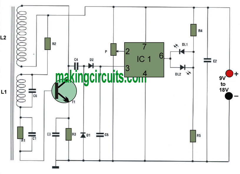
This metal detector circuit can be used for tracing out or locating concealed wires, nails, tubes or other similar metallic materials under a layer such as under walls, grounds, basements, wood furniture etc.
This gadget functions to identify metals of a specific dimensions from a distance of about 18-20 cm if correctly optimized.

One amongst its primary uses is to sense the existence of metallic tubes (water tube, gas tube, electric cable, etc.). Identifying these is very beneficial when drilling or fitting nails on walls.
At any time a identification is conducted, the machine has to be calibrated as depicted below:
1) Keep the sample metal part of near the coil at some reasonable distance
2) Adjust potentiometer P entirely to the right, such that the RED LED just lights up
3) Turn the potentiometer to the left until the RED LED just turns off and the GREEN LED illuminates.
The detector is then ready for use. Keep in mind that calibration has to be repeated every once in awhile.
At any time the detector picks up the existence of metals, the RED LED illuminates and the GREEN switches off.
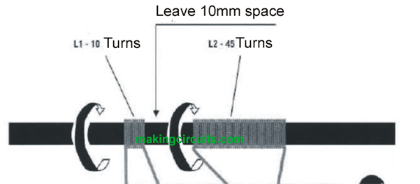
The coils L1 and L2, wrapped on the ferrite bar, must be completed meticulously, following cautiously the instructions of the diagram.

Two simple 9-volt batteries are as much as necessary to power the equipment. To cover the gadget, it is suggested Never to utilize metallic housings.
PCB Design for the metal detector


Parts List for the above metal detector circuit for locating underwall metals
All resistors are
Of 1/4 watt except if mentioned otherwise mentioned
R1 = 1 M
R2 = 47K
R3 = 1 K
R4 = 330
R5 = 330
PI = 10K
CI = 1 nF disc
C2 = 0.1 uF disc
C3 = 0.1 uF disc
C4 = 0.1 uF disc
C5 - 47 nF disc
C6 = 0.22uF.
D1 = M117
D2 = AA117
DL1 = Red Led
DL2 = Green LED
IC1 = UA741
T1 = BC237
Wire diameter 0.3 mm
l Ferritede = 8X10
1 IC socket 8 pins
Holder for 9 volt battery
2) Another Metal Pipes, Nails, and Cables Detector
The device highlighted in this article assists to maintain items as secure as it can be by serving the DIY hobbyist find pipes and cables tucked in walls.
It's also employed to find tiny components of metal which are inserted in walls or in woodwork, for instance screws and nails.
Really it is a kind of metal detector, meaning that it may never discover non-metallic items like plastic pipes.
Several units with this common sort are excellent at locating small pieces of metal near to the search coil, however are practically "blind" to huge pieces of metal except if also, they are near to the detector coil.
Alternatively, various other units are fantastic at getting big items some distance from the lookup coil yet provide minor reaction to smaller components of metal even at almost "point blank" range.
This cable detector features outstanding sensitivity to equally minor and major items, turning it into similarly ideal for seeking small nails just beneath the surface or pipes buried 50 to 100 millimetres into a wall.
The unit is entirely compact and is also powered from a PP3 size battery. When metal is detected there exists a clear signal from a moving coil meter, which provides an improved reading for ferrous metals or a minimized reading for non ferrous metals.
Its capability to differentiate relating to the two sorts of metal may not be of any sort of good significance in the present framework, however I assume it can be helpful on events.
How the Circuit Works
The entire circuit diagram for the Cable Detector project is found in below mentioned diagram. IC1 is utilized in the oscillator stage, which is a conventional 555 astable circuit.

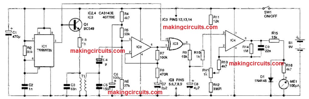
The values of R1, R2 and C2 supply an nearly squarewave output at a frequency of about 20 kHz.
Which includes kinds of metal locator it has an benefit in employing a fairly high frequency, however this really does not apparently provide a considerable enhancement in sensitivity using a phase shift detector.
For any locator which will be put to use like a "treasure" locator there exists a particular gain in having a low frequency.
Employing a low frequency generally removes ground effect issues. Quite simply, it eliminates difficulties with the detector being triggered somewhat once the search coil is near to the ground, even though there isn't any metal in the ground.
In the present context this can be an advantage, since the walls of a house could generate very similar trouble.
Tests on the prototype cable detector developed no visible change in the meter reading with the search coil inserted beside walls, people, or other non-metallic items. 01 is needed as an emitter follower buffer amplifier at the output of the oscillator, and this also makes the main winding of the search coil (T1) through current limiting resistor R3.
The primary and secondary windings of the search coil are recommended in parallel tuned circuits, with C3 and C5 behaving as their particular tuning capacitors. C4 couples the output of the secondary winding to a high gain amplifier based upon functional amplifier IC2.
This particular stage is an easy non inverting amplifier acquiring a voltage gain of a little over 200, that is adequate to make sure that the solid output signal through T1 is intensely clipped.
This generates virtually a squarewave signal which is effective at generating one input of the phase detector (IC3). The other input of 103 is driven direct through the output of 101. IC3 is a CMOS quad 2 input XNOR gate instead of an XOR type, however it still supplies the needed reaction to changes in phase difference.
An XNOR gate is properly just an XOR sort getting an inverter at its output. The two input signals to IC3 come in anti phase hence the average output voltage is low below standby situations, rather than in phase so that a high average output potential is generated.
This will be significant since the DC amplifier at the output of the circuit is built to cope with a little offset on the output from the lowpass filter.
The latter is a single stage passive circuit (R9 and C8) that passes into a non inverting amplifier dependant on IC4. The closed loop voltage gain of this stage is a little under 200.
Under standby conditions the output voltage through the filter will probably be under one volt, however this can be still more than enough to deliver IC4's output totally positive.
This can be prevented by getting the negative feedback circuit hook up to the wiper of RV1 instead of to the 0 volt supply rail. RV1 is modified to offset the DC bias on the input signal and use the output voltage of 101 down to about one volt. ME1 is provided through the output of IC4 via series resistors R15 and R16, which provide a full-scale sensitivity of around two volts.
Under quiescent conditions the meter as a result reads roughly half fullscale. D1 shows that there isn't any greater than quite minimal overloading of the meter if the output of IC4 goes highly positive.
Remember that the output amplifier is dependent on IC4 being an operational amplifier that could work effectively in single supply DC amplifier circuits.
Almost every other functional amplifiers never will function correctly in the IC4 position of this circuit.
The current usage of the circuit is around 10 milliamps. A common PP3 size battery is simply about sufficient to supply this, plus its not essential to work with some sort of "high power" battery.
3) Stud Finder Circuit
The next circuit below also explains how to build a stud finder circuit specifically designed to locate metal hidden pipes under walls, concrete beams, bathroom tiles etc
One of the biggest issues when doing work on walls is the presence of concealed water pipes, gas pipes or electrical conduit, which are hard to detect. This circuit will make the work easy by enabling quick detection of any hidden metal pipe of obstruction below the wall.
How the Circuit Works


The circuit works on the principle that metal absorbs magnetic energy when exposed to a magnetic field.
The sensor L1 is a part of the transistor T1, which is an LC oscillator of frequency about 15 kHz. The alternating voltage across the LC circuit reduces when energy is drawn by a metallic object from the magnetic field surrounding L1.
Inductor L1 can be built by winding 500 turns of enameled copper wire over a ferrite rod having a length of around 200 mm and diameter of 10 mm. The thickness of the wire can be around 0.2 mm to 0.3 mm
The voltage is rectified in IC1 and the direct voltage thus obtained is supplied to the differential amplifier IC2.
An on/off indication can be produced upon comparing this with the voltage pre-fixed by P3. D4 extinguishes when there is metal in the proximity of L1. P1 and P3 help to adjust the sensitivity of the detector.
Power is supplied to the circuit through the 9 V battery PP3.
How to Calibrate
Calibration of this metal pipe detector is done by setting P1 for full resistance and fitting an oscilloscope to the collector of T1.
Now adjust P2 to control the peak value of the oscillator to the point where it is just on the verge of stopping.
Check this by modulating P3 to the point at which the LED can just light up. On holding a coin near the ferrite rod, the oscillator should stop working and the LED will no longer be lit.
The detection process may be initiated by setting with P1 at maximum resistance, ie, the lowest oscillator peak value, and the wiper of P3 at earth, ie, the lowest trigger level. On approximately locating the pipes, increase both the peak value and the trigger level to the desired accuracy point.