


Despite the fact that SPWM are typically deemed the simplest way of replicating and enacting a moderately pure sine waveform, the point that it will probably not emulate or overlap with a real sine wave causes the design to be somewhat elementary, especially when judged against a Multi Level cascaded sine wave inverter theory.
We are able to evaluate and investigate the two sorts of sine wave simulation principles by looking at the following graphics:

You can easily identify that the Multi level cascaded principle generates a far more noticeable and effectual demonstration of a real sine wave compared to the SPWM idea which counts entirely on coordinating the RMS significance with the primary sine wave level.
Developing a standard Multi Level Cascaded sine wave Inverter can be hugely challenging, however the theory which is discussed below allows the application more convenient by employing common ingredients.

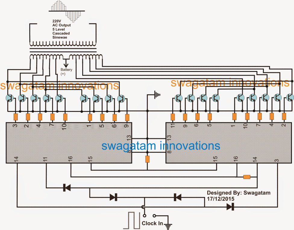
Multi Level Cascaded Sine Wave Inverter Circuit
Parts List
All resistors are 10k, 1/4 watt
All diodes are 1N4148
All BJTs are TIP142
ICs are 4017
With reference to the figure above, we are able to observe just how easily the multilevel cascaded inverter principle may be realistically enforced by means of just a muti-tap transformer, a few 4017 ICs and eighteen power BJTs, which can be readily swapped with mosfets if desired.
At this point a couple of 4017 ICs that happen to be Johnson's 10 stage counter divider chips, are cascaded to churn out a sequentially moving or following logic highs across the outlined pinouts of the ICs.
These sequentially moving logic are utilized for activating the associated power BJTs in an exact progression which subsequently switch the transformer winding in a manner which then causes the transformer to construct a cascaded design of sine equivalent waveform.
The transformer makes up the core of the circuit and engages a specifically wounded primary with eleven terminals. These terminals are simply taken out uniformly from one extended worked out winding.
The BJTs connected with one of the ICs trigger one of the halves of the transformer by means of 5 taps making it possible for the procreation of multi level rectangles, constituting one half phase of the AC waveform, at the same time the BJTs in connection with the second ICs performs the parallel operation to structure up the lower 50% AC cycle through a 5 level cascaded waveform.
The ICs are powered by clock signals put on the shown state in the circuit, that can be procured from any regular 555 IC astable circuit.
The initial five units of the BJTs develop the five numbers of the waveform, the remaining four BJTs transform the corresponding in opposite sequence to accomplish the cascaded waveform obtaining an overall of nine skyscrapers.
These skyscrapers are produced by bringing forth an climbing and diminishing voltage stages by the switching of the interacting winding of the transformer which happen to be calculated at the appropriate voltage ranges
For instance, winding #1 could possibly be calculated at 150V with reference to the central tap, the winding #2 at 200V, winding #3 at 230V, winding #4 at 270V as well as winding #5 at 330V, therefore when these are flipped in sequence by the range of the indicated five BJTs, we obtain the initial five numbers of the waveform, after that as these winding are powered in opposite by the following four BJTs it results in the sinking 4 level waveforms, consequently implementing the top part of the half cycle of the 220V Alternating current.
The identical is duplicated by the alternative nine BJTs involved with the other 4017 IC contributing to the lower half of the five level cascaded AC, which accomplishes 1 full AC waveform of the preferred 220V AC output.
Transformer Details:


As could be spotted in the earlier mentioned plans, the transformer is a traditional iron core variety, manufactured by winding the primary and the secondary using winding equivalent to the suggested voltage taps.
Whenever linked with the matching BJTs these winding could be anticipated to generate a five level or an overall of nine number of cascaded waveform in which the initial 36V winding may well correspond and stimulate a 150V, the 27V may well trigger the exact same of 200V, while the 20V, 27V, 36V could well be committed of causing 230V, 270V and 330V across the secondary winding in the presented cascaded structure.
The group of taps on the lower hand of the primary may well implement the changing over to finish four ascending amounts of the waveform.
An equivalent operation may be replicated by the nine BJTs in connection with the interrelated 4017 IC for developing the negative 50% sequence of the Alternating current...the negative is provided on account of the reverse adaptation of the transformer winding with reference to the middle tap.