

There are numerous potential applications currently to explain the use of a noise level meter - for example, monitoring the sound output at dances, discos etc.
The unit explained in this article was developed mostly to establish the noise level generated by model engines.
How the Circuit Works
It has five switched ranges from 70 dB to 120 dB in 10 dB steps and is readable to '/j dB.The prototype was located to be precise to ± I dB.The circuit for the noise level meter is displayed in figure 1.

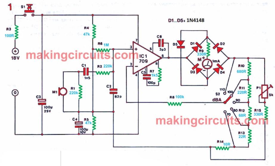
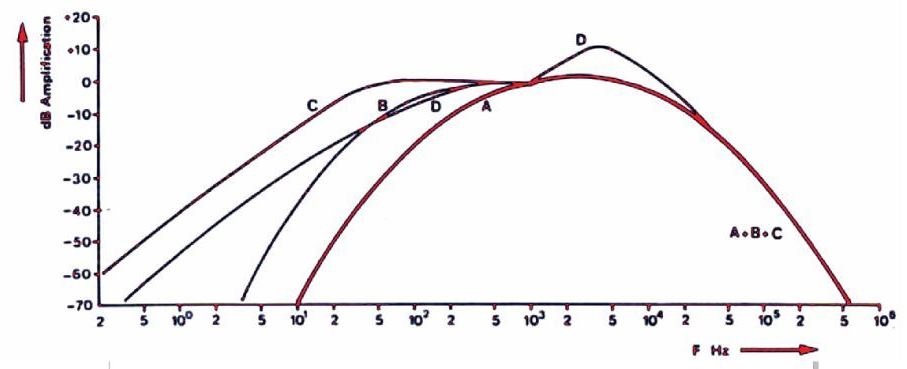
The audio signal is located by the microphone M1 and filtered by the network C1, C2, R1 and R2. These components, together with the capacitance of the microphone and the input impedance of the amplifier, make certain that the frequency reaction of the system is fixed to match the internationally standardised ' A' weighting curve shown in figure 2.

This 'weighted' signal is then fed to the operational amplifier A1, the gain of which can be modified by S2 to provide five noise ranges.
The AC output of the op-amp is then rectified by diodes D1, D4 and fed to the meter via resistor R9.
As this rectifier is included in the comments loop the meter reading stays linear over the whole scale.
Diode D5 is included to restrict the current through the meter to a safe value, thereby reducing the chance of destruction in case a ' loud' noise is measured on a ' quiet ' range.
Components C5, C6 and R7 are incorporated to offer frequency compensation and to avoid instability.
Under standard procedure the noise level meter circuit will simply draw about 2 mA, so it can be run by two PP3 (or identical) batteries. The push-button switch S1 shows that the circuit is not accidentally left on.
The meter ought to be calibrated in dBs and should have a full scale deflection of + 10 (normal log scale).