

In this post we are going to discuss a few non-contact voltage detector/tester circuits for checking the presence of active mains live wire. We will be understanding what non-contact voltage detector is, how it functions and how to make one using transistors and ICs.
What is non-contact voltage detector?
Non-contact voltage detectors are AC mains tester which can be used to check the presence of active live wire without touching the wires physically. Traditional voltage tester has metallic tip which need to touch with live wire physically.
Non-contact voltage detectors are much safer way to test AC mains and it reduces risk of electric shocks while working at high voltage situations.
The non-contact voltage detectors has antenna for picking up the leakage current on active live wires. The leakage current flow through antenna and fed to very high gain amplifier. The amplifier output goes high when it detects weak electrical signals. The amplified voltage can be interfaced with LED or buzzer.
So, can we completely throw off traditional voltage tester? NO! Non-contact voltage detectors need an external power which is usually a battery. Battery may die any time without a warning and circuit board may also fail as well but, it is less likely to happen and usually non-contact voltage testers available in market are equipped with battery indicators.
So due these minor limitations, it is always good idea to carry a traditional voltage indicator along with non-contact voltage indicators.
Now you would have a clear idea what non-contact voltage indicators are all about. Now let’s construct our own non-contact voltage tester which is good enough to detect active live wire during electrical works.

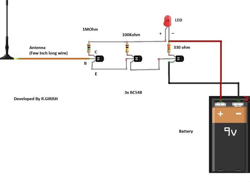
Here is a basic one, when it detects AC mains the LED glows, if it detects faint electrical signals the LED glows dimly.
The circuit consists of very high gain amplifier which has 3 transistor connected in Darlington pair configuration.
The antenna is an insulated wire which is few inch long. The circuit can be enclosed in a plastic junk box with insulated antenna wire hanging outside.
Please add a LED indicator and switch to the circuit, the LED indicator will avoid confusion to user whether the circuit is active or not while testing AC mains.
The battery should last for few months with normal usage. The sensitivity of the circuit is directly associated with battery voltage so, regularly replace the battery.
Below given circuit is the extension of the above simple circuit. It gives visual and audio response. The LED lights up and the speaker buzz when it detects the presence of active mains live wires.

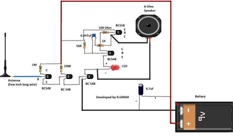
This circuit has similar structure as first circuit does; it has three transistors in Darlington pair configuration for amplifying weak leakage current from AC mains. The LED is replaced by buzzer circuit and LED is also present in this circuit too.
The buzzer circuit is very simple oscillator consisting of two transistors and few passive components. If it detects strong signal it buzz loud and if it detect weak signal it buzz faintly.
Using IC:

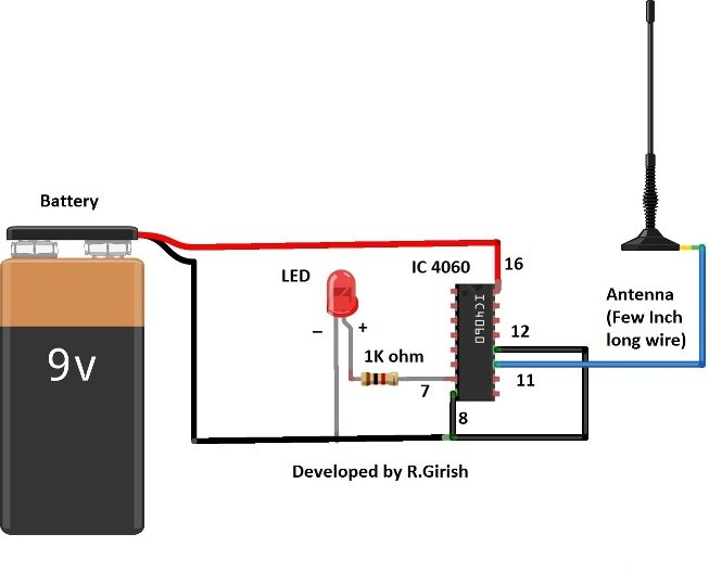
The above circuit is using IC 4060 which is timer IC. The LED blinks if it detects any electrical signal around the antenna; it blinks at the rate of 3Hz. If no electrical activity is detected the output either stay high or low.
We all know that the digital ICs are susceptible to noise easily, taking advantage of this we can achieve similar functionality of firstcircuit. This IC based circuit is even more sensitive than first two circuits.
IC 4060 is not the only IC which is sensitive to AC mains; there are other ICs which are sensitive to AC mains.
If you have any question regarding non-contact voltage detectors, feel free to ask in the comment section.