The submit addresses a circuit method which can be utilized to automatically switch and adjust the more powerful counterpart along with the solar panel, battery and the grid such that the load constantly becomes the optimized power for an disrupted error for procedures.
6 KWH signifies around 300 to 600 watts per hour, suggests that the solar panel, the inverter, the charge controller all ought to be optimally rated for handling the previously listed load problems.
Right now as far as dividing and optimizing current from the solar panel directly and/or battery is concerned, it might not necessitate advanced circuitry somewhat could be executed utilizing properly rated series diodes with each of the sources.
The source which generates higher current and fairly lesser voltage drop is going to be permitted to perform by the specific diode in series while the other diodes stay turn off.....as soon as the current source starts depleting and goes below any of the other source's power levels the pertinent diode will now override the earlier source and takeover by allowing its power source to conduct towards the load.
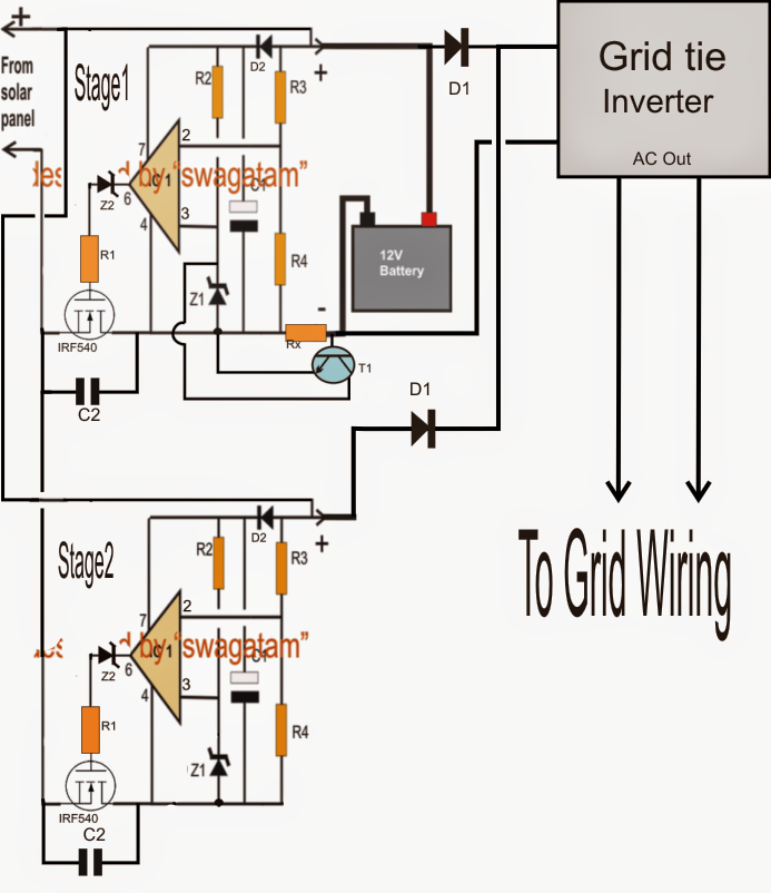
We might understand the whole process with the aid of the following diagram and presentation:
Talking about the above grid, solar panel optimizer circuit, we are able to notice two basic identical stages making use of two opamps.
The two stages are precisely identical and form two parallel linked zero drop solar charge controller stages.
The upper stage1 contains a continuing present function as a result of the existence of the BJT BC547 and Rx. Rx might be chosen implementing the following formula:
0.7x10/Battery AH
The above aspect guarantees a proper charging rate for the attached battery.
The lower solar charge controller is without a current controller and feeds the inverter (GTI) instantly by means of a series diode, the battery also attaches with the inverter by way of another individual series diode.
Both the solar charge controller circuits are created to produce the maximum fixed charging voltage for the battery along with the inverter.
Provided that the solar panel has the capacity to obtain peak sun light it overrides the battery voltage and permits the inverter to make use of current instantly from the panel. The methods also enables the battery to get charged from the upper solar charge controller stage. On the other hand as the sun light commences depleting the battery overrides the solar panel input and provides the inverter with its power for carrying out the operations.
The inverter is a GTI which is fixed with the grid mains and contributes in sync with the grid. Provided that the grid is more effective the GTI is permitted to be inactive which correspondingly avoids the battery from obtaining drained, in spite of this in the event that the grid voltage falls and turns into inadequate for powering the associated appliances, the GTI takes over and commences satisfying the deficiency by means of the conneced battery power.
Components list for the above solar, grid optimizer circuit
R1 = 10 ohms
R2 = 100k
R3/R4 = see text
Z1,Z2 = 4.7V zener
C1 = 100uF/25V
C2 = 0.22uF
D1 = high amp diodes
D2 = 1N4148
T1 = BC547
IC1 = IC 741
R3/R4 needs to be picked such that its junction geneartes a volatge which might be just more than the set refernce at pin2 of IC1 when the input supply is simply over the optimal charging level of rthe hooked up battery.
For instance guess the charging voltage is 14.3V, then at this voltage R3/R4 junction ought to be simply greater than pin2 of the IC which may 4.7V on account of the provided zener value.
The above needs to be set utilizing an aritificial 14.3 V external supply, the level could be modified correctly as per the preferred battery voltage
