

The LDR based interruption counter circuit explained in this project is a circuit that will count how many times an opaque object intersects between a ray of light and an optical-sensor. The counting or the data is viewable over a three seven segment displays, permitting a pratical count up to 999 objects.
The counter makes use of LDR as a sensor or photocell. The light may come from a natural source (sun) or artificial (incandescent, fluorescent, neon lamps, etc.).
Once the count gets to its maximum limit (999), the circuit restarts it again at 0 and delivers an overflow signal which you can use externally to extend the count length to 4 or more digits.
The circuit additionally offers the facility to erase the account (reset) or end it (stop) whenever you want. It does not apply moving parts and is incredibly compact, due to the usage of a digital technique called time division multiplex.
When there is no physical contact between the sensor and the external world, the device ensures zero mechanical wear and enables counting objects of all kinds, no matter what their shape or weight may be. This is among its most important advantages.
Photoelectric meters are utilized in a wide selection of applications, household and commercial, and upgrade conventional electromechanical meters in several circumstances. They may be accustomed to count people, animals and items such as leaves, bottles, cans, boxes, bags, etc.
How it Works
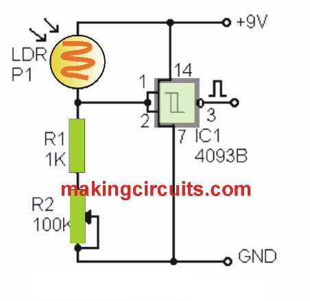

In the figure above we can see the pulse shaper circuit. Under standard circumstances, the light source illuminates the LDR causing its resistance to drop. As a result, the input of the Schmitt-trigger inverter gets a stop and its output becomes low.
As soon as an object interrupts in between the light beam and the photocell, the resistance of the photocell goes high, implementing a low to the input of the Schmitt-trigger inverter. Responding to this, the output of the circuit forces a changeover from low to high, that is, it creates a rising edge.
Once the object ceases to interrupt the light beam, the resistance of the LDR drops and the output of the NAND gate gets low yet again. The overall outcome of this course of action is the release of a positive voltage pulse. This pulse triggers the counter.
The photocells will not react instantly to changes in the intensity of the incident light and, consequently, produce slow impulses. Because of this a Schmitt-trigger NAND gate is employed as a pulse shaping system.
The potentiometer R2 enables modifying the sensitivity of the LDR based on the intensity of the available light. Resistor R1 functions as safety, protecting against excessive current from streaming when the potentiometer is in its lowest resistance position and the LDR is lit up.
The pulse counter becomes the center of this project. It is configured around the IC 4553. This chip contains 3 BCD meters attached in cascaded form.
The first counter records, in BCD code, the units, the second the tens and the third hundreds of the amount of pulses.
For instance, in case you have entered 319 pulses, the BCD code 0011 (3) is going to be written in outputs of the first counter, code 0001 (1) in the outputs of the second counter, and code 1001 (9) in the outputs of the third.
These 3 codes are cycled sequentially in the outputs of the IC 4553 counter, each one of these showing up for a tiny proportion of time (1.6 ms). This approach of promoting digital information is called multipLex by time division.
The outputs of the meter supply a decoder 4543B, which switches each BCD code into a seven-segment code that sequentially triggers the displays responsible for switching ON the digital units, tens and hundreds of the account.


The second figure above displays the complete schematic diagram of the photoelectric counter. The pulses from the shaper are placed on pin 12 of IC 4553. For the counting process to initiate, the MR (master reset, pin13) and DIS (inhibitor, pin11) lines has to be both low.
To begin the counting from 000 or abort it whenever you want, press the delete button S1 (RESET). In this manner, the line MR (reset masterpin 13) of the IC 4553 obtains a stop and all BCD outputs of its internal counters are reset to 0000.
To quit the counting and lock it at the given last registered value, without deleting it, you need to press the stop button S2 (STOP). When this is carried out, the DIS line (inhibitor, pin 11) of the IC 4553 is ended and the procedure of the internal BCD counters is inhibited.
The capacitor C1 ascertains the scan frequency, that is, the rate with which the IC 4553 displays sequentially in its outputs the codes of the units, tens and hundreds of the current count data.