

The most common phase testers show if an AC mains voltage is present at the wall output. They are typically known as the Live (L) connection. This useful AC mains socket outlet tester circuit can test all these and more, using just four resistors (double the two resistors in series to have the voltage load on each resistor), two bi-color LEDs and a pushbutton.
The whole circuit can be housed inside a normal 3-pin plug that comes with an Earth connector. However, you must ensure the circuit is contained in the plug housing and the pushbutton is rated at AC line voltage.

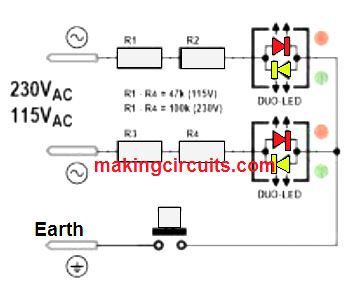
If the socket tester is attached into an AC power outlet, the pair of LEDs must be lit to display there is a current flow between the live (L) and the neutral (N). The color of the LED is not so significant as long as both bicolor LEDs are lit, therefore making the overall color to be orange. It is important to remember that the bicolor LEDs have been identified to prevent an extra diode. This part would be coupled in anti-parallel connection in case a single LED was utilized.
Once the pushbutton is pressed, only one of the LEDs will illuminate. This represents the power outlet Earth connection that is accurately wired. The lit LED also shows the Live (phase) connection.
Warning: This circuit may have discrepancy in the indications when expected to work as-is from the schematic due to the connection of the Neutral (N) and Earth/Ground lines. This connection also differs across several national electricity codes and associated guidelines for electrical safety.