

It takes a lot of time and effort to tune a guitar, particularly if your hearing has been affected by loud music or you don't have good ears. However, there is a diy option available that you can easily create and will let you to tune your guitar without having to listen to it.
With a 1 Hz resolution, this guitar tuner is a highly precise tuner. It relieves the need to tune each string from the tone produced on a lower string that has already been tweaked, allowing the performer to pluck and twang away at a flawlessly tuned guitar.
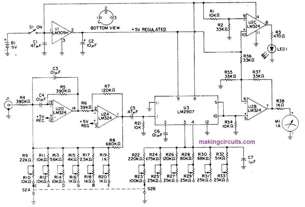
The latter approach could lead to a guitar that is not tuned effectively. A 9-volt transistor battery supplies power to this standalone guitar tuner. Each of the guitar's strings may be tuned to the desired wavelength using a six-position rotary switch on the device. To use the circuit, connect your guitar's cord to the phono jack, choose the appropriate string, and set your instrument such that the meter reads center scale.
A battery sensor circuit that measures the battery's terminal voltage is also included in this guitar tuner circuit. LED1 illuminates to let the user know that the battery needs to be replaced when it lacks adequate power to run the tuner circuit. This function guarantees correct voltage, which in turn ensures accurate tuning indications. Although it may appear complicated, the theory underlying this idea is really straightforward.
Harmonics Not Considered
Harmonic-rich tones are produced by all stringed instruments. An electrical guitar tone's basic frequency has to be enhanced and its harmonic content decreased in order to produce a pure sine wave in order to be measured. By doing so, the frequency sensitive portion of the circuit is able to just react to the fundamental frequency and ignore the harmonics.
This is accomplished via sections D and A of U2, which are operational amplifiers coupled as an active bandpass filter.
This dual feedback circuit amplifies the target frequency while attenuating all other frequencies outside the passband through both negative and positive feed-back. By choosing the appropriate resistive component, the passband of the filter may be tuned to the required frequency.
Six potentiometers and resistors work together to choose the circuit's center frequency. R9 through R20 are the part numbers for these components. They're selected by S2A.
The U3 integrated circuit is a specialized frequency-to-voltage device made to generate a DC voltage proportionate to the frequency of the input signal.
The resistance between pins three and four and the capacitance linked to pin two together define the output voltage level of this semiconductor. The front panel selection switch, together with a collection of six potentiometers and resistors, control the resistance linked to U3 pins three and four, much like it does with U2D and U2A.
R22 through R33 and S2B are the part numbers for these components. U2B is utilized as an operational amplifier with a gain of three and a DC voltage added to its negative input to give a wider meter scale for improved meter sensitivity.
A milliammeter is driven by U2B via R 38, producing a meter scale that represents a center scale frequency range of 10%. This sensitivity is enough to detect a 1 Hz variation in the guitar.

How the IC Pins Functions
To check the battery's terminal voltage, section of the IC U2C is wired as a voltage comparator. A part of the battery voltage is given to negative input pin 9, while a reference voltage of +5 volts is provided to pin 10.
Pin nine is kept at a greater potential than pin 10 while the battery is new because of the terminal voltage. LED1 is turned off as a result, and the output of IC U2C is zero.
The voltage at pin nine will eventually equal the voltage at pin 10 as the battery voltage drops with consumption. Thereafter, the output changes to battery voltage (high) and turns on LED1.
IC U3 and IC U2B get a steady voltage from the 5-volt regulator IC U1 to maintain the guitar tuner's precision. In spite of the battery's continually varying terminal voltage, the circuit will continue to operate with its calculated precision.
Do not Substitute the Capacitors
Avoid using ceramic capacitors in place of C3, C4, and C6. To maintain the calibrated accuracy of the device, these components, which are employed in the frequency-sensitive portions of the circuit, must be reliable components.
You might choose to replace the resistors marked with an asterisk (*) with metal film resistors if you want the highest testing consistency. Use a little quantity of epoxy to affix the LED to the front panel securely. The LED's leads should not be bent, and a couple of flexible wires with multiple colors should be soldered to it.
The front panel above the meter is a practical location for mounting the 9-volt battery. Make a tiny battery clip out of sheet metal if you like, and attach it to the panel using screws or glue.
To prevent it from dangling, fasten the battery to the front panel. The guitar tuner circuit should be calibrated using a precise audio frequency generator and an oscilloscope (or VOM).
If you don't have access to these devices, take the unit to your nearby electronics repair shop and get it calibrated there.
How to Set up
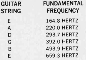
Set the audio oscillator to 165 Hz and the rotary switch to the lower E position. For a precise meter reading at the middle of the scale, adjust R23. Set the audio oscillator and rotary switch to the relevant locations, tweak the corresponding potentiometer for the other five notes, and repeat the process.
Use a regular phono plug to interface the audio generator's output to the circuit's input socket in order to calibrate it. Adjust the generator's amplitude to 20 millivolts RMS and frequency to 165 Hz.
If the amplitude control of the audio generator somehow doesn't allow you to select such a value, add a 10,000-ohm and a 470-ohm resistor voltage divider across the output of the oscillator, set it to 0.5-volts RMS, and drive the circuit with the voltage across the 470-ohm resistor.
Switch on the tuner's power, adjust the rotary wheel to lower E, and check the waveform at pin one of IC U2. R10 should be adjusted for the 165 Hz signal's peak amplitude, which is approximately 0.15 volts RMS.
Adjust the audio oscillator to each of the other frequencies in a similar fashion. Configure the rotary switch to a particular note and use the appropriate potentiometer to set pin 1 of U2's waveform's peak amplitude.
To use the device, connect the guitar wire to the front panel jack and flip the power switch. The rotary switch should be set to lower E, and the guitar's volume controls should be at their highest setting. Strike the guitar's bottom string.
Tune the guitar until the meter precisely reads the center of the scale. (The correction might not be finished the first time you pull the cord.) Each string should be adjusted similarly after setting the rotary switch to each of the remaining settings. When tuning is complete, remember to switch off the power button.
The guitar tuner circuit may be adjusted to match the keyboard in case you have a brand new rock band and often use an electric organ or piano.
Start by connecting the circuit to the keyboard and lowering the volume. Turn up the volume gradually until you obtain a readout. Strike a low A.
You must tune the A potentiometers until the reading is dead centered. Repeat the same with the remaining notes. This tuner may be set to the frequency of your preference and therefore you can pick up the acoustic hash of other devices (odd harmonics).

You are now ready to utilize your finished guitar tuner circuit. You won't ever have to worry about those warbling or klunker chords you may have once pulled again when you have this guitar tuner in your possession.