

This circuit can be used to convert an AC signal into DC output with extremely high precision.
The post explains a simple precision rectifier circuit using just two opamps.
This precision rectifier operates from an asymmetrical supply, handles input signals up to 3 Vpp and has a frequency range that extends from DC to about 2 kHz.
How the Circuit Works
Its amplification is unity, and depends mainly on the ratio R4/R3. Opamp A1 is connected as a voltage amplifier (Ao=l), Az as an inverting amplifier (Ao:-l). Opamp Az, transistor T1 and diode D2 ensure that the output voltage, U2, is identical to the positive excursions of the input voltage, U1.

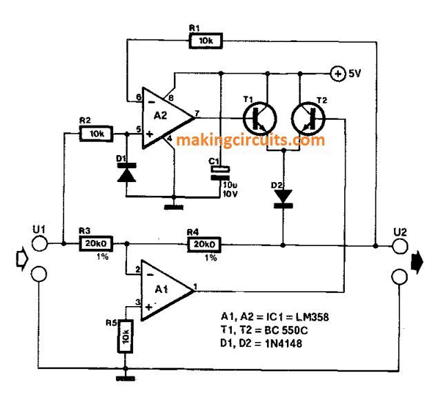
When U1 is positive, the out- put of A1 is held low at about 0.25 V, so that T2 is disabled and can not affect the rectified out- put signal.
Components R2 and D1 protect the pnp input stage in Az against negative voltages, which are effectively limited to -0.6 V.
For negative excursions of the input signal, the function of A1, T2 and Dz is similar to the previously mentioned components.
The peak output voltage . of the rectifier circuit is determined mainly by the maximum output swing of the opamps and the voltage drop across the transistors plus D2: this amounts to about 3 V in all.
When the circuit is not driven, it consumes about 1 mA, and is therefore eminently suitable for building into portable, battery- operated equipment.