


The post points a PWM speed controller circuit for a fan air blower system to be utilized in Biomass cook stoves. The circuit also consists of an continuous automatic battery back-up supply with an built-in automatic battery charger circuit for the specific application.
According to the demand the biomass cook stove application needs a 12 V fan for turning air into the combustion chamber for the preferred enhanced outcomes, this induction of air ought to be adjustable, which means the fan speed really should have a manageable function by means of a PWM control knob, which might be utilized by the user for setting/selecting the most wanted air induction and rate of combustion.
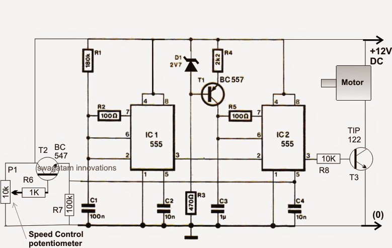
A novel 12 V PWM fan speed control circuit is demonstrated below, utilizing several IC 555.
IC1 is utilized for producing a 80 Hz square wave frequency which happens to be utilized at pin2 of IC2 organized as a PWM generator. IC2 produces a changeable PWM at its pin3 by initially transforming the pin2 square wave input into triangle waves across C3 after which by evaluating it with the voltage level employed at its pin5.
The pin5 voltage which can be physically selectable or variable through pot decides the duty cycle of the PWMs which often establishes the linked fan speed appropriately.
The adjustable voltage or the flexible PWM pot is created by P1, together with T2 rigged in the typical collector mode.

The above described fan speed controller really should be operated by means of an uninterruptible power supply system from a standby well-recharged battery back up stage.
The battery consequently usually requires an automatic battery charger circuit to ensure that it remains prepared for offering an immediate nonstop power to the fan, being sure a smooth and a nonstop supply to the motor and feed of air to the biomass cook stove.
Each one of these problems are satisfied in the following circuit diagram which happens to be an opamp based automatic battery charger circuit.
The charger circuit as presented below uses a number of opamps for the needed detection and cut-off throughout the battery full and battery low level thresholds.
The 10k preset attached at pin3 of the left 741 IC is placed such that at any time the battery touches the full charge level the output of the IC just goes high deactivating the appropriate TIP127, cutting off the charging voltage to the battery.
The glowing LED implies charging ON circumstance of the battery and vice versa.
The right hand side IC 741 phase is placed for supervising the low voltage condition of the battery. When it arrives the lower threshold, pin2 of the IC turns into less than the reference pin3, which inturn leads to the output of the IC to go high deactivating the connected TIP127. The load now is inhibited from obtaining any power from the battery.This threshold cut off is set by modifying the 10k preset at pin2 of the IC
Here too the base LED signifies the pertinent circumstances, glow implies battery low, while shut-off signifies battery above the lower threshold.

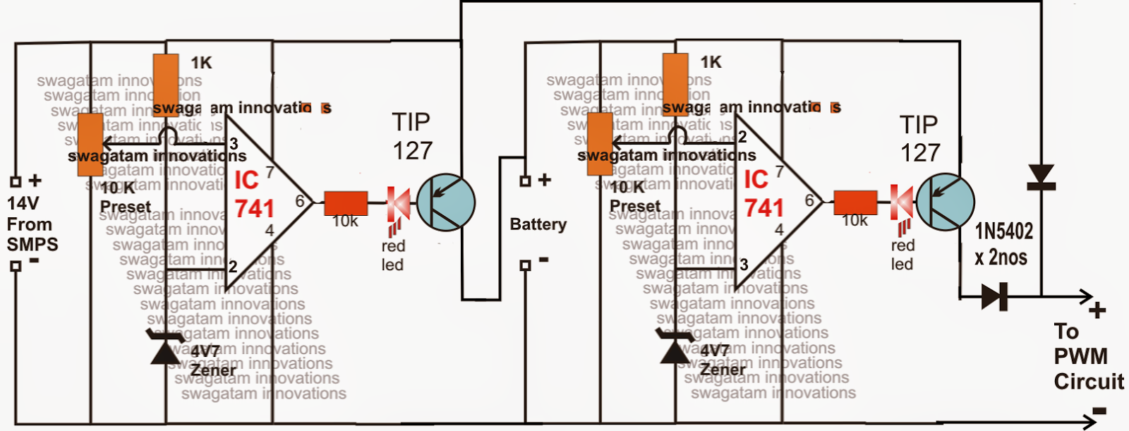
The two diodes are associated with a particular purpose, while the mains is found the 14V supply from the SMPS being somewhat higher than battery voltage maintains the horizontal diode reverse one-sided and permits only the SMPS voltage to achieve the load or the fan blower by means of the vertical 1N5402 diode.
In the event when mains voltage breaks down, the horizontal diode associated at the collector of the right hand side TIP127 immediately gets forward not balanced changing the dead SMPS supply with the battery supply, confirming an continuous flow of the supply to the fan.
The 14V transformerless SMPS could possibly be purchased ready made from the market or developed personally. A couple of appropriate circuits might be observed in the following links:
12V 1 Amp MOSFET SMPS
12 V SMPS using VIPer22A IC
12 V SMPS using TNY tiny switch IC
All the above models will have to be tweaked at their output phases for obtaining the essential 14 V.
