

Radon is a radioactive gas that is naturally emitted from the earth's surface and it is basically inert. It's an odorless, colorless, and invisible byproduct generated due to uranium's radioactive decay. It easily goes into the atmosphere from the ground, because it is inert and does not chemically interact with substances. Radon can be emitted practically anywhere on the planet, although based on the particular geology and soil porosity, certain geographical places may have significant levels than others.
As radon decays and releases other short-lived isotopes known as daughter products or progeny, it turns into a health hazard. The most common type of such chemically active isotopes is in the form of charged particles (ions). They stick to other materials easily, including dust and smoke pollutants. Table 1 summarizes a part of the radon 222 decay chain as well as its brief progeny.
When radon decomposes, alpha particles with 5.5 million electron volt energy are released (5.5 MeV). That may seem like a lot, however alpha particles can only penetrate 4 to 7 centimetres (1.5 to 2.5 inches) in air until they completely lose their energy due to ionization. Alpha particles can be easily stopped by using a piece of paper or perhaps even with human skin.
Thus, unlike beta particles, gamma rays, X-rays, or even ultraviolet light, direct exposure to radon presents no harm to people. Nevertheless, radon does poses an indirect health risk. When people breathe radon-contaminated air, the energized alpha particles can induce cytotoxic effects to the thin layers of lung tissue.
When combined with the effects of cigarette smoke in the lungs, this damage has the ability to induce lung cancer. There are numerous types of radon, however the most common is radon 222, which is the most concerning to doctors and health researchers. The number 222 corresponds to the isotope number of the element. Radon and its progeny release alpha particles, which give rise to helium nuclei.
The bulk of radon 222 inhaled is either quickly exhaled or absorbed into the circulation, where its alpha emission causes no apparent harm. Nevertheless, radon's short-lived descendants, like polonium 214 and polonium 218, are more prone to release alpha particles, which can harm susceptible human organs.
The alpha particles produced by the decay of polonium 218 carry a mass of 6.0 MeV, whereas those produced by polonium are with a mass of 7.7 MeV, both of which are greater than the 5.5 MeV of radon 222. As a result, scientists think they are the main participants responsible for causing lung cancer in instances where radon 222 levels are judged to be exceeding recommended safe range.
For centuries, radon has remained an element of the atmosphere. Only when devices to detect and quantify it were invented did humans become aware of its presence. Due to the alarming figures on lung cancer deaths, its existence is a cause for worry. Its existence has long been suspected to be a role in such deaths. However, distinguishing cancer caused alone by radon from cancer caused solely by smoking tobacco or smoking in the presence of radon is complicated.
Units of Measurement
Specific activity, or the quantity of radon in the atmosphere, is calculated in picoCuries per litre (pCi/l). This translates to 2.22 disintegrations per litre of air every minute. The average radon content in the outdoor air is between 0.1 and 0.2 picocuries per litre. At a level of roughly 15 inches, radon gas has a concentration of 100 pCi/1. According to the Environmental Protection Agency (EPA), radon levels of 4 pCi/l or less in a house pose almost no health risk.
If greater concentration levels are observed, this has issued guidance for particular measures to be implemented. Follow-up monitoring in other parts of the house is one of them. Nonetheless, in the lack of a medically validated absolute safe threshold value for radon exposure, it is solely up to the individual to choose how much radon level is appropriate for his apartment. According to documented risk assessments, a radon concentration of 30 pCi/I is equivalent to inhaling two packets of cigarettes each day in terms of cumulative hazard.
Ionization chamber Layout Concept
Detecting the high-energy alpha particles that radon produces as a byproduct of radioactivity is the simplest approach to identify its existence. The alpha particle possesses a kinetic energy of roughly 5.49 MeV, which ionizes the air travelling past it. To ionize air, roughly 34 eV is necessary in general. Considering that an alpha particle loses all of its energy by ionizing air, approximately 100,000 (105) electron-ion pairs are formed along a 4 cm travel length (1.5 inches).
Due to this , the electric field within the ionization chamber can effectively accumulate a charge of 10-14 coulombs.
Since this ionization chamber can be simply constructed from an aluminium beverage container, it gets a cylindrical shape. It features a wire anode that runs through the middle of the can and is positively charged. Positively charged ions (+) are drawn to the positively charged cathode cylinder lining, whereas negatively charged electrons (e) are pulled to the positively charged anode and reach a few microseconds after an ionizing process. The ions reunite with electrons from the high-voltage supply source just few milliseconds afterwards.
A brief voltage spike is generated across the resistor in series with the power source as a result of a current flow. Thereafter, this pulse is amplified, detected, and counted through an electronic circuit. To calculate particular radon activity in units of pCi/l, we can multiply the number of counts per minute by a constant that involves the effective volume of the chamber.
The collection rate is increased by the presence of radon "daughters" generated in the chamber. The design of the beverage can ionization chamber depends on the consideration that the air inside the chamber is a true representation of the air in the room which is being monitored. The air in the ionization chamber is gently circulated via apertures in the container through convection.
Dimension of the Ionization Chamber
The ionization chamber is made from a 350 ml aluminium beverage can since its size is standardized and it is readily available. Because of the size homogeneity, ionization calibration may be done based on dimension of the chamber. The size of the can allow alpha particles to expend the majority of their energy by ionizing air. As noted previously, the intensity of the current pulse captured on the anode is determined by the quantity of charge generated.
In a chamber of this size, ionization generated by beta particles and other naturally occurring radiation, especially gamma rays, creates smaller intensity pulses. This makes it simpler to distinguish between bigger alpha ionization pulses and those induced by beta particles, gamma rays, and amplifier distortion.
High-voltage power source
To create an electric field between the anode and the cathode, a minimum yet constant 500-volt difference is necessary. Above a voltage range of 200 to 1000 volts, the ion collecting efficacy of this chamber stays rather unchanged. Regrettably, any noise created by the 500-volt supply would be intrinsically linked with the amplifier input. This also sets a threshold of fewer than 100 microvolts for total noise, ripple, and short-term drifting.


A charged, 0.1 uF metallized-polypropylene-film capacitor provides high voltage. A good capacitor will keep its charge for the last several weeks, which is adequate to power the ionization chamber. Once the 9-volt battery is replaced, it must be recharged. The ionization chamber's high-voltage capacitor should be charged via a suitable source before it can be used. (We'll go over alternative techniques for achieving the needed voltage afterwards.) The high-voltage source should be dependable and not a cause of electrical noise.
How the Circuit Works
The design for the amplifier is shown in Figure below.

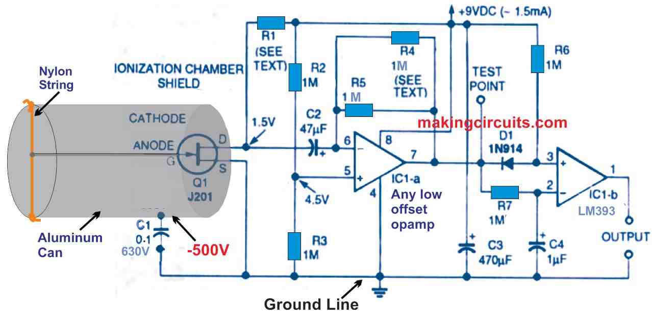
To ensure higher amplifier input signal, the capacitance should always be kept as low as possible. This is accomplished by joining the anode wire of the chamber directly to the gate of JFET Q1. Excessive capacitance and leakage current, which would have been available if the interconnection had been made using a PCB, are removed. The overall input capacitance is kept to roughly 7 picofarads using this method. A 1 millivolt charge is applied to the gate of Q1 by an input pulse. The charge on the gate should be sustained for some period of time to enable the amplifier to respond.
To get a decent signal-to-noise ratio, an input resistance big enough to establish a lengthy pulse width would contribute far more thermal disturbance. Allowing the FET gate to remain hanging in the chamber or self-bias has been used to prevent this problem. As a result, input impedance is increased while noise is reduced. Since gate leakage drives the gate more toward the drain-to-source voltage, a JFET could be self-biased. The gate operating voltage is maintained by a current of around 1 picoampere when the JFET is operated with just 1 to 2 volts from drain to source.
Both of the above methods eliminate the possibility of using a PCB to link the gate to the anode. An alpha ionization creates a huge 100-millisecond pulse which is 20 to 40 dB stronger than the amplifier's distortion with this arrangement. The drain resistor and feedback resistor should be adjusted to match the individual JFET utilized, which is the main disadvantage of this system.
Furthermore, when power is introduced, the amplifier might require several minutes to settle. After you complete the first calibration processes, you can adjust the given values of various parts to optimize the suggested ionization chamber efficiency. Since this amplifier would often operate at ambient temperature, thermal stability is not a major problem. The ionization chamber's overall calibration is quite consistent, even with rather broad ambient temperature variations, and is independent of the amplifier gain adjustments.
The right side op amp is a voltage comparator, whereas the left side op amp is a low-power, low-offset operational amplifier. Both devices can work across a broad variety of voltages through a single power supply (3 to 32 volts). The current drain is 600 microamperes, which is practically independent of the supply voltage. After the JFET's transconductance stage, the associated op-amp acts as a current-to-voltage converter. The voltage increase is around 60 dB on an average. However, owing to the impedance modification, the amplifier power increase is over 160 dB! The JFET's input should be electrically isolated from the op-output amp's to avoid regenerative feedback.
How to Select R1 and R5
The value of the drain resistor R1 will be determined by the parameters of the J201 JET (Q1) that will be utilised in the circuit. With a drain-to-source voltage of roughly 1.5 volts, short the JFET's gate to its source and measure the drain-to-source current IDS. Then, using this current and the voltage of the power supply you wish to utilise, calculate the drain resistor value:
R1 is the drain resistor, and its value is = (Vs - 1.5)/IDS.
R1 should be between 10 and 33 kilohms for a J201 FET and a 9-volt battery. Use 1-megohm resistors for both parallel resistors R4 and R5 while building the amplifier. Both resistors axial leads should be formed and soldered such that R5 remains permanently in place while R4 may be easily removed during the calibration procedure. Gain could be modified later by shunting 1-megohm resistor R5 with a different value for resistor R4 until an optimal value is obtained by doing so.
To serve as a test point for an alligator clip lead or oscilloscope probe, connect a tiny tinned wire to the output pin 7 of the left side op-amp. To function as a handy circuit common or ground lug, place a solder lug beneath one of the sheet metal screws holding the circuit board in place on the end of the container. The configuration of the remaining components is not crucial, except from the constraint on Q1's placement on the circuit board. To finish wiring the circuit, use the appropriate pad positions bridged by the parts you've chosen, as well as any additional jumper wires.
Except for JFET Q1, complete the insertion and soldering of all components on the circuit board. On the solder -pad side of the board, solder the source and drain leads of JFET Q1. Then delicately bend the gate lead away from the other two leads so that it is perpendicular to the circuit board's solder pad side. Solder a 4-inch piece of bare copper wire (28 to 32 AWG) to Q1's gate lead and stretch it so it is perpendicular to the circuit board. Cut the anode wire's free end to a length of about 4 and 1/2 inches. Solder the junction after twisting a tiny loop (approximately 1/16 inch in diameter) on the end of the anode wire.