

Have you ever wondered how your reactions compare to those of other people? This reaction circuit is designed to do just that, it will show scientifically which of the two people playing the game has the most rapid reactions.
It should be stated here that a person 's reactions do not seem to bear any relationship to any other facet of their character. Some people who are generally considered to be dull-witted have very fast reactions and some bright and alive people have very poor responses. This is mentioned straight away in order that no one will try to draw unwarranted conclusions from the results.
One or two facts do emerge however. The reactions of the young are very much faster than those of an older person and anyone who has had even 2 small amount of alcohol is at a distinct disadvantage.
How the Circuit Works
There are two distinct parts to the fastest draw game circuit. Tr1 and Tr2 form a random indicator to signal the players to start in much the same way as a referee fires a shot to start an event, in this way the electronics provide a.n impartial starter.

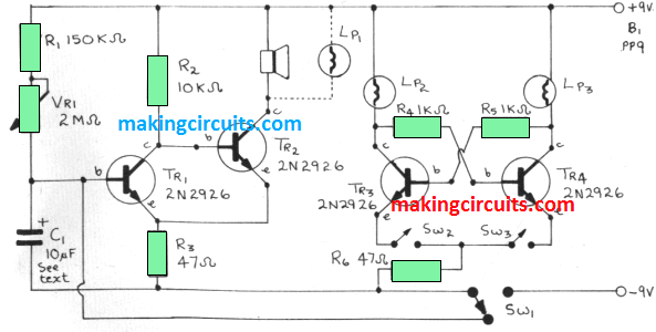
There are two alternative ways in which the start signal can be indicated. A loudspeaker can be included to produce a loud click or a light bulb can be made to switch oft. Once the circuit is switched on there is a time delay before either of these happen and this time delay can be varied.
Tr1 and Tr3 are connected up as a Schmitt Trigger circuit. When the unit is oft, SW1 is arranged to short out the capacitor Cl. When SW1 is thrown Cl charges up through R1 and VH1.
Initially the potential across C1 will be very low but at a certain point it will reach a level when Tr1 is beginning to turn on. This transistor will then start to draw current and so the potential across the emitter and the collector will tall, this in turn reduces the emitter-to-base voltage of Tr2, less current is then drawn by R3 so the voltage will drop at that point. This increases the emitter-to-base voltage of Tr1 which in turn switches itself further on. All of this takes place very quickly and this current is such that when Tr1 is on, Tr2 will be turned oft and vice versa.
The loudspeaker or bulb in the collector circuit of Tr2 will thus have a reduction of current passing through it. In the case of the loudspeaker this will result in a loud click and in the case of the bulb it means that it will stop glowing. When SW1 is turned oft‘ this shorts out C1 so that the game can start again.
The operational part of the circuit is very simple and comprises two transistors, two bulbs, three resistors and two switches. Each player has control over one of the switches, either SW2 or SW3. Say that SW2 is made first of all.
This will mean that the supply voltage appear across the transistor which will be biased through R5 and LP3. When this transistor is turned on the voltage at the collector drops to very low level. If SW3 is then made it will also have the supply potential across it but R4, which provides the bias to the base, will have its other end at a very low potential and so the transistor can not be turned on.
The converse applies it SW3 is made before SW2. Whichever player makes his switch first also makes it impossible for the second player to light his lamp. This action is also very, very quick and even if there are imbalances in the resistors and transistors used these will not give any advantage to either player. It comes down to whoever makes their switch first, lights his own bulb and the action of the other switch becomes irrelevant.
How to Play Fastest Draw Game
The idea is that as soon as the signal from the starter is made, both players try to make the switch as fast as possible and the lighted bulb indicates who was faster, even if there is one ten-thousandths of a second separating them.
The reason for offering alternative start signals is that people's re- actions vary with the type of stimulus. Some are fast with light and not with sound although there is usually very little in it but if two players are very evenly matched it will sometimes show that one is faster on one rather than the other.
A small switch could be included to select either the loudspeaker or the bulb. Another interesting effect that has been noticed is that some people are very much better than others if a long time delay is used, while they may not be good on short time delays.
The knob on VR1 should preferably be of the type without any pointer and ideally it should be twiddled around by a third person (though this makes little difference). The time delay available is about 15 seconds with the loudspeaker and somewhat less with the bulb, if the time delay needs to be increased C1 can be raised in value. Note that the component chosen for C1 should have very low leakage and a tantalum type is to be preferred. If it does have high leakage the circuit may not work.
Components List
- R1 = 150K ohms
- R2 = 10K ohms
- R3 = 47 ohms
- R4 = 1K ohms
- R5 = 1K ohms
- VR1 = 2M ohms linear
- C1 = 10uF 25V - See text