

If you looking for a screaming alarm circuit that would produce a high pitched ear piercing kind of alarm sound, then probably this design will be just suitable for your need.
Alarm is commonly known system that generates loud noise. They are widely applied in factories or by military and police authorities, and even on ambulance. Sirens can be designed in various way, and based upon the design of the circuit, its output vary. This project will explain one of a type of alarm called screaming alarm, and unlike other siren type, it generates siren based amount of light reaching the circuit. Screaming Alarm is often referred as Light Activated Alarm Circuit.
How it works?
Screaming light entirely depends upon the strength of light. The more strong the light to the circuit, the sound increases. As the light generates an impulse into the circuit, therefore when the light is high it will produce more sound. IC 555 timer is the mother in this type of circuit design as it helps to generate oscillation depending upon the amount of light received by light dependent resistors.
The following diagram Figure 1.0 illustrates the circuit design:
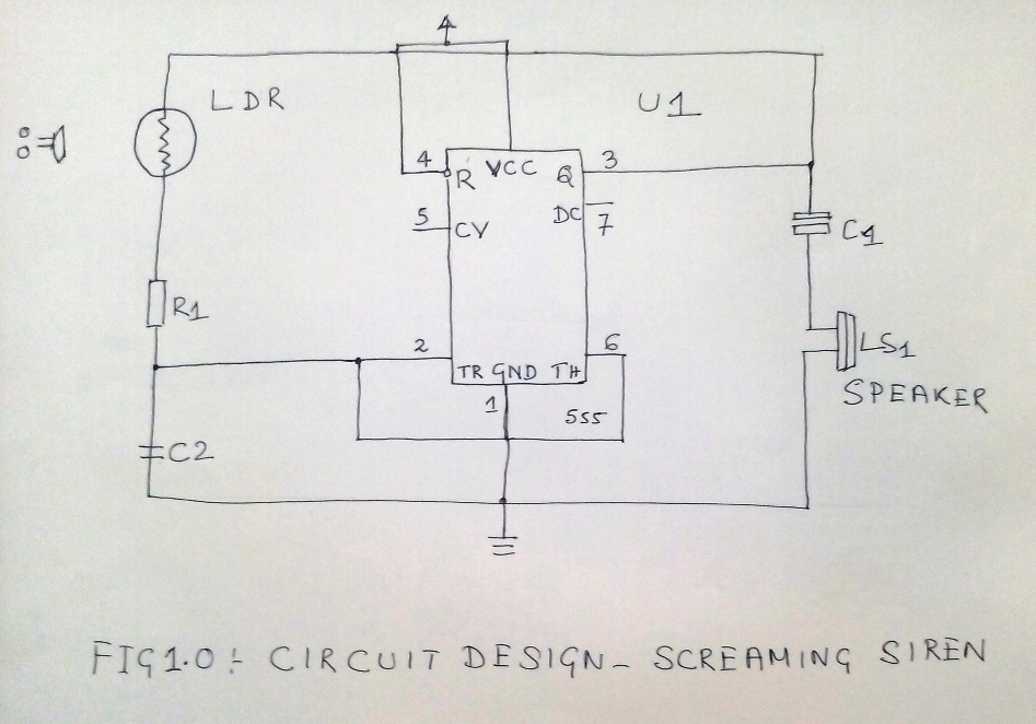

The principal IC 555 timer used in this circuit generate oscillation that is necessary to run the system. As the timer can be applied on three different mode: Monostable, Astable and Bistable, here we have used astable form to avoid any external triggers. The Pin 4th pin in the circuit is connected to 8th pin on 5V voltage supply. The 3rd pin via C1 capacitor is connected to the speaker and the 2nd pin of IC is attached to the 6th pin.
Following the astable pattern, here Pin 2 which is connected to Pin 6 enable trigger the circuit in continuous fashion. As the VCC is supplied with voltage of 5V this initiates charging C2 capacitor via LDR and R1 resistors. When the capacitor attain 2/3rd of VCC, Pin 3 gets triggered and further discharges via R1, thereby generating the pulse. Again when the capacitor reaches 1/3rd of VCC, it initiates charging.
Besides the timer, the light dependent resistor is another crucial component. By principle a light dependent resistor shows high resistance on no light, the resistance gets reduced once it starts receving light. Here we also used 2 mega ohm photo resistors, and the two LDR resistors along with 1K ohm resistor maintains serial connectivity. They are further connected to C2 capacitor [100nf]. The two pins on 6th and 2nd are shorted, and is connected to C2 capacitor. The another part of the capacitor has its ground connection.
The speaker is also another important material to design the circuit as it helps to transfer the signal from electric to physical state, by acting as a transducer. As the speaker has two type of magnets - permanent and moving, they helps to convert the electrical signals into vibrations, which gets generated by the IC 555 timer. In this project we have used one speaker of 8ohms which is connected to the output of Pin 3 of the 555 IC via C1 electrolytic capacitor. The positive section of the capacitor's terminal is connected to Pin 3 of the IC while the negative is connected to the speakers positive node, and grounded.
What you need?
Following is a list of component that you need to procure to make this LDR operated screaming alarm circuit:
- IC 555 timer
- speaker
- DC battery
- Light dependent resistor
- Breadboard
- Wires for connection
- R1 resistor
- Capacitors – C1, C2
Operating the Circuit
To operate the screaming alarm circuit connect the circuit to the breadboard and apply power of 5V. Keep the LDR on dark zone and this will fail to produce output. Now place the LDR in light, and you can then hear the sound. Apply more light, the sound will go high.