


The submit teaches a straightforward IC 555 focused PWM solar battery charger circuit that immediately places and modifies the charging voltage as a reaction to the fading sunlight circumstances, and attempts to preserve an optimal charging power for the battery, no matter the sun ray intensities. The connected buck converter guarantees an effective conversion to ensure that the panel is not exposed to demanding problems.
I have previously mentioned one fascinating solar PWM based MPPT kind solar charger circuit, the following design might be regarded an improved version of the just like it may include a buck converter phase producing the design all the more economical than the earlier counterpart.

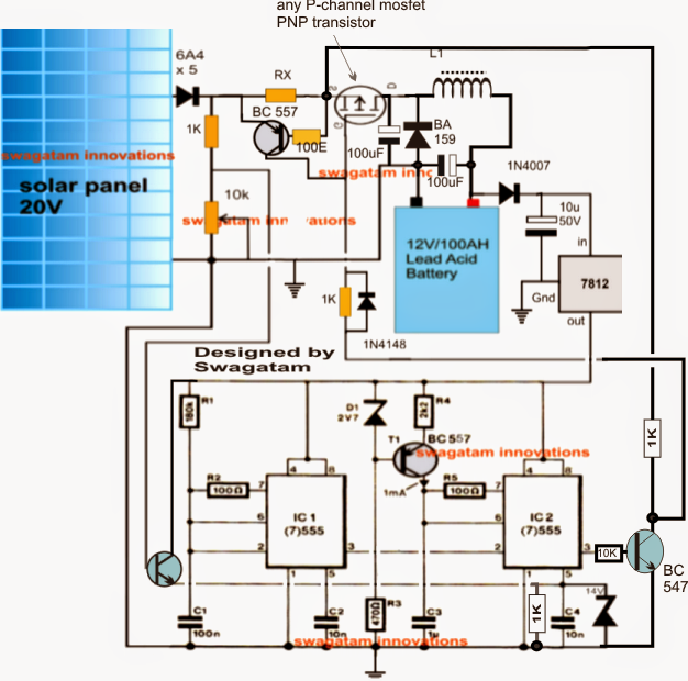
Note: Make sure you hook up a 1K resistor across pin5 and ground of IC2 for proper working of the circuit.
The offered solar PWM buck charger circuit could be grasped with the aid of the following reason:
The circuit includes three simple phases viz: the PWM solar voltage optimizer utilizing handful of IC 555s in the the form of IC1 and IC2, the mosfet PWM current amplifier and the buck converter employing L1 along with the relevant parts.
IC1 is rigged to generate a frequency of around 80 Hz while IC2 is set up as a comparator and PWM generator.
The 80 Hz from IC 1 is given to pin2 of IC2 which makes use of this frequency for producing triangle waves across C1.... which can be even more compared to the immediate potentials at its pin5 for dimensioning the proper PWMs at its pin3.
The pin5 potential as might be observed in the diagram, is resulting from the solar panel by means of a potential divider level and a BJT common collector stgae.
The preset located using this potential divider is originally properly modified such that at the peak solar panel voltage the output from the buck converter generates the optimal magnitude of voltage suiting the attached battery's charging level.
As soon as the above is placed remaining is managed instantly by the IC1/IC2 stage.
In the course of peak sunlight the PWMs get correctly hardened being sure minimum stress on the solar panel yet creating the right optimal voltage for the battery as a result of the existence of the buck converter phase (a buck boost type of design is easily the most effective procedure for lowering a voltage source without disturbing the source parameters)
Right now, as the sun light starts reducing the voltage across the set potential divider also commences to drop consequently which can be found at pin5 of IC2....on detecting this constant deterioration of the sample voltage IC2 sets out broadening the PWMs in order that the buck output has the capacity to sustain the necessary optimal battery charging voltage, this means that the battery goes on to obtain the correct amount of power irrespective of the sun's retarding illumination.
L1 ought to be dimensioned correctly such that it yields the estimate maximum voltage level for the battery when the solar panel is at its peak requirement or put simply when the sunlight is in the best possible position for the solar panel.
RX is launched for figuring out and limiting the highest charging current limit for the battery, it might be determined by making use of the following formula:
Rx = 0.7 x 10 / Battery AH
The way to establish the circuit.
Presume a 24 V peak solar panel is chosen for charging a 12 V battery, the circuit could be set as directed below:
In the beginning do not hook up any battery at the output
Hook up 24 V from an external C/DC adapter across the points where the solar panel input will have to be provided.
Hook up a 12 V for the IC1/IC2 circuit from another AC/DC adapter.
Regulate the potential divider 10k preset until a potential of around 11.8 V is accomplished at pin5 of IC2.
Subsequent, by way of a few trial error tweak and boost the variety of turns of L1 until a 14.5 V is calculated across the output where the battery ought to be linked.
That's all! the circuit is currently set and prepared to be utilized with the meant solar panel for obtaining an optimized highly economical PWM buck based charging methods.
In the above design I have attempted to put into practice and remove an oppositely different voltage and current output from the the circuit with regards to the sunlight, in spite of this a deeper investigation made me understand that really it should not be replying oppositely somewhat corresponding to the sun light.
Simply because in MPpT we want to draw out maximum power throughout the peak hour while also to be certain that the load fails to hog the panel and its effectiveness.
The following amended diagram now can make a much better sense, let's seek to examine the design immediately:
In the above updated design I have produced the following vital change:

I have added a NPN inverter at pin3 of IC 2 to ensure that now the PWMs from IC 2 has an effect on the mosfet to take out maximum power from the panel and decreases the power slowly as the sun light decreases.
The PWM pulses together with the buck converter ensures a perfect compatibility and maximum power extraction from the panel, but reduces steadily in accordance with the sun's reducing strength.
In spite of this, the above set up guarantees about one significant element, it guarantees a balanced input/output power ratio which happens to be consistently a key issue in MPPT chargers.
Even more in the event the load attempts to draw out an incredible amount of current, the BC557 current limiter instantly arrives into action avoiding the disturbances of the smooth performing of the MPPT by cutting off power to the load in the course of those periods.
